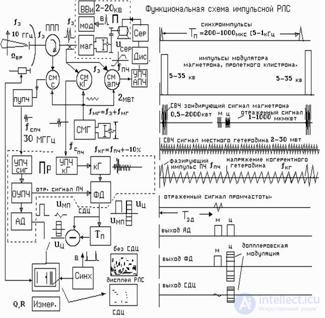
Studying a specific functional scheme of a coherent-pulse radar will allow the student to illustrate the interaction of its systems and devices: antenna-waveguide system, transmitter, receiver, devices for ensuring coherence, etc.
Aps
The antenna-feeder path is simplified. It consists of a mirror antenna with a powering device and a circulator . A discharger may be placed at the receiver input for additional protection of the receiver against high-power transmitter pulses.
Transmitter
Transmitter on tunable magnetron. The restructuring is performed on a mechanical electric drive. It moves the piston of the microwave chamber of the magnetron.
A high-voltage power supply and a pulse modulator are necessary for the operation of the magnetron .
Local oscillator
The local oscillator contains a low-power microwave generator and a stabilizing resonator.
As a rule, these elements are mounted on a heavy platform, protected from acoustic noise and vibrations. The frequency can be tuned by the resonator piston.
Receiver
The receiver path starts from the receiver mixer, where the reflected signals and the local heterodyne voltage are received. The mixer is usually combined with an intermediate frequency preamplifier (IFC). From it, the amplified signal is fed through a cable to the main intermediate frequency amplifier (OUPCH). The HRBT has amplitude and phase detectors.
HRA
The requirements for short-term drift frequencies of the local heterodyne are large ( see Lecture 3.4.). Therefore, the automatic frequency control works on a magnetron. Part of the transmitter power from the coupler and the local heterodyne is fed to the mixer mixer. The intermediate frequency amplifier frequency converter contains a frequency detector. If the transmitter and local oscillator frequencies are not equal to the intermediate frequency, a voltage will appear at the output of the frequency detector. It will increase and go to the servo motor. The engine will rebuild the piston of the magnetron and adjust the frequency to the desired value.
Coherent heterodyne channel
The radio pulse of the transmitter begins to generate the microwave frequency *** of an arbitrary phase. These are the properties of a magnetron. therefore passive interference from the terrain will have a random (noise) initial phase and a very wide spectrum falling into the SAD filter band. Suppression area will not.
In order to fix the initial phase of the magnetron, a coherent heterodyne (CG) is used.
Part of the transmitter power is supplied to the KG mixer . The amplified transmitter pulse at the intermediate frequency is fed to the KG. The coherent local oscillator remembers the transmitter phase. The reflected signals and voltage of the coherent heterodyne become mutually coherent.
System СДЦ
AT coherent pulse radar passive interference from the terrain at a wavelength of 2-5 cm have a low-frequency modulation in the region of 4-20 Hz. Thus , with a pulse repetition period of about 200 µs, at the output of the FD phase detector, the previous pulse differs little from the current one. If the pulse is delayed for the period following T n and subtracted from the current one, then a zero can be obtained at the output of the subtracting device. Signals from the terrain will be suppressed and not observed on the radar screen.
Doppler frequencies of signals reflected from airplanes are 1-2kHz. Therefore, at the output of the FD, the previous pulse is very different from the current one . At the output of the subtracting device, a signal of a moving target is formed, which is observed on the radar screen.


Comments
To leave a comment
Radio Engineering Systems
Terms: Radio Engineering Systems