Lecture
The purpose of the lecture is to familiarize with those antennas that are most often used in practice. These are classes of simple and complex mirror antennas, as well as slotted, stripline. Radar uses a variety of antennas. The purpose of the lecture is to teach the student to deal with the device of various antennas.
Plan
An antenna selection approach. 20 minutes.
Class of mirror antennas. 20 minutes.
The class of "flat" antennas. 20 minutes.
APPLICATIONS. 20 minutes

The type of antenna for the radar is selected on the basis of a number of considerations. Sometimes they are contradictory.
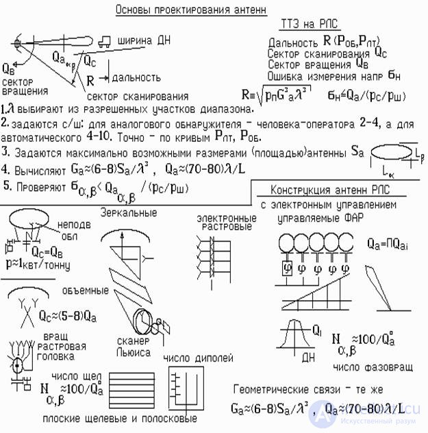
In the radar equation, the power of the reflected signal increases in proportion to the square of the production of the gain by the wavelength G a 2 l 2 . To achieve a given range of R, it is advantageous to use an antenna as large as possible. On the large aperture of the antenna, you can get a large gain G a and due to this, reduce the transmitter power. For example, a twofold increase in G a will reduce the transmitter power fourfold (see the radar equation).
They are used exclusively in cheap household radars. This radar patrol patrol services and alarm systems.
They are used in radars with a slow view of space, for example, 4-10 degrees per second. Radar PSN-1 and PSNR-5 Russian-made equipped with such antennas. Their main advantage is ease of manufacture, and the disadvantage is a significant amount of space due to the remote irradiator. For a quick view of the space requires a large power drive, since the review is made by turning the entire antenna column. For the rotation of the column required engines with a capacity of 5-10 kW per 1 ton of mass. If fast rotation is not required, then it can be limited to one kilowatt.
However, due to the ease of manufacture, the antennas are widely used in airfield stations and radar air defense systems.
If you place the N horns in the focal plane and feed them alternately, you can make the scan quickly enough. For convenience, the waveguides from each fold and ring. Formed structure, which is called the "raster head." A waveguide rotates inside the ring of the horn head. He performs the scan.
To extend the Q c viewing area, Lewis scanners are often used. It is characterized by the use of a narrow metal mirror placed at 90 degrees. relative to the focal plane. The design forms a waveguide "scarf". Here, to move the feed horn, not just along the focal plane, but across. And if this "kerchief" is turned into a "snail", forming an annular gap, then the feeding horn can be rotated. This design allows you to expand the sector of the scanning of the DNA to 50 radiation patterns. This type of antenna is used in the SNAR radar.
The relative bulkiness of the mirror antennas did not find their use in the class of portable radar and radars of guided missiles. More compact slit and strip.
Slot antennas are designed in the form of a flat wave of waveguides. Radiating slits are cut in each waveguide. They form a diagram in the horizontal plane. The vertical plane is determined by the number of waveguides vertically.
Powering the waveguides is performed by a waveguide power distributor. To facilitate the antenna, the waveguides are made of plastic, followed by metal sputtering. Often, the waveguide and distribution parts are molded from plastic at the same time and covered with a common aluminum sheet with slots.
Strip antennas are the cheapest. On foiled Teflon is applied drawing from dipoles with feeder powering. Then Teflon is etched. The remaining strip-dipole structure forms a DND. She covers a rectangular metal or metallized resonator. The antenna turns out flat and compact. Such an antenna is used in the radar of the SSR 3. Scanning of space is performed by rotating the whole structure.
When solving a number of tasks, a very fast (less than 1 millisecond) transfer of a ray from one point of space to another is necessary. For example, when multichannel accompaniment of many goals. These are anti-aircraft defense tasks, firing marks for firing positions. Make it mechanically impossible. For this, electronically controlled systems have been developed. NxM emitters are placed on a flat surface in the form of dipoles or miniature shafts with electronic phase shifters. Each phase shifter can change the phase of a signal emitted into space. Using a computer, it is possible to calculate the phase state of each phase shifter, which will provide the desired direction of the beam. Each phase shifter receives from the computer a command to set the phase and in this way a phase front is formed in the aperture of the antenna.
The switching time of the electronic phase shifters can be 10-50 µs.
Phasoarashchateli and control system are very expensive items. One phase shifter can cost up to $ 100. As shown in the figure, to ensure the beam only in one plane, N = 101 / Q a phase shifters are necessary. For the formation of the bottom 2 about x 2 about in two planes
It will take 50x50 = 2500 pieces. Taking into account the price of one PV, the total cost of one web can be 250 thousand dollars.
test questions
1. Is it advantageous to increase the antenna gain and why?
2. How is space scanning organized by the antenna?
3. How does the Lewis scanner work?
4. What are the Lights for and how they work?
Comments
To leave a comment
Radio Engineering Systems
Terms: Radio Engineering Systems