
Lecture
The goal of functional-structural analysis can be to improve the functioning of both individual components and the technical object as a whole, as well as to identify shortcomings in the TO and formulate tasks for their elimination.
For conducting a system-structural analysis, two models can be proposed that complement each other.
1. A structural diagram in the form of a graph (see p. Error: Reference source not found), which reflects the interconnection of the identified components.
2. A tabular model, in which a description of the functions, the nature of the connections between the components, and the results of the analysis are given, i.e., it is used for conducting a substantive analysis.
When conducting a functional-structural analysis of technical systems, two approaches can be distinguished: the operational and the subject-based.
In the operational approach, the object of analysis is the functions (operations) performed by the technical object and its components. Therefore, in the structural model the vertices of the graph denote the functions performed by the TO as a whole and its components. And the edges reflect the relation between functions. For example, the model shown in Fig. 9.3 reflects the subordination of functions.
In the subject-based approach, the object of analysis is the components of the technical system. Therefore, in the structural model the vertices of the graph denote the components of the technical system, identified according to some characteristic. And the edges reflect the connections between the identified components, either structural (ensuring the structural integrity of the TO) or functional (ensuring the performance of the MUF).
As has been noted, all technical objects can be conditionally divided into two groups: technical objects whose functioning is directed at transforming flows of substances, energy, and signals, and static systems, representing quite rigid structures, whose MUF is to determine the mutual arrangement of structural elements and preserve their shape under the action of external loads (see p. Error: Reference source not found).
The study of technical systems of the first and second groups has certain features. First of all, with regard to the models used.
For modeling a TO of both the first and the second group, various structural models can be used, the application of which depends on the features of the TO, its structural complexity, and the nature of the problem being solved.
1.2.1. Operational approach
The basis of the operational approach is a hierarchical model, which reflects the co-subordination of functions in the formation of the MUF (Fig. 9.3).
The performance of any function entails the appearance of undesirable effects (UE) – everything has to be paid for. Therefore, it is advisable to conduct the analysis of functions using a model in the form of a graph-tree, which has received the name of the Ishikawa – Sibiryakov diagram. This diagram reflects both the functions performed and the possible UE that they entail (Fig. 9.5).
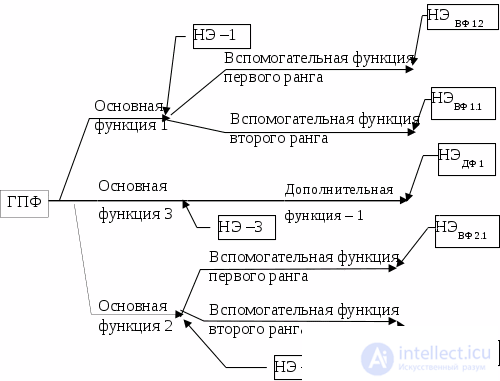
Fig. 9.5 Analysis of functions using the Ishikawa–Sibiryakov diagram
This model helps focus attention on the search for undesirable effects (UE), on revealing the socio-technical contradictions corresponding to them, and thereby makes it possible to outline a number of problems that need to be solved.
Naturally, UE appear once the physical operating principles and the technical solutions of the components that perform these functions have been outlined. Undesirable effects are not obvious, they are not immediately visible, and this model helps to focus attention on searching for them.
If a prototype exists when developing a new TO, then this model (Fig. 9.5) allows one to take a systematic approach to its analysis in the functional aspect. It helps the developer to be distracted from the specifics of the prototype, using it only as a stimulus. In his reasoning, the categories of functional components are replaced by categories of thinking at the level of functions. This makes it easier to overcome the vector of psychological inertia caused by the presence of a prototype.
Functional analysis must begin with constructing a hierarchical model of the relations between functions (Fig. 9.5). Then, in the technical system, identify the functional components and carry out an analysis of the functions they perform.
Since the purpose of creating a TO is to perform the MUF, functional components must be identified in relation to the MUF.
When conducting a functional-structural analysis and searching for possible directions for improving a TO, the following recommendations can be used.
1. Imagine and formulate the ideal technical solution for the technical object as a whole and for its components.
2. In accordance with the principle of correspondence between function and structure, assess the level of performance of the functions for the identified functional components at a qualitative level: insufficient, adequate, excessive.
Adequate, – if a change (an increase or a decrease) in the parameter characterizing this function leads only to a deterioration of the function performed.
Insufficient, – if an increase in the essential property characterizing this function leads to an improvement of the function performed.
Excessive, – if a decrease in the parameter characterizing this function leads to an improvement of the function performed.
Analysis of technical objects shows that functional excess is quite often encountered in technical objects. To eliminate this, one must imagine what would happen if this component were absent, i.e., abolish it?
Use the STC operator (see p. Error: Reference source not found) – increase or decrease the function performed (the technique – quantitative changes). Analyze how this will affect the performance of the nearest higher-level function.
If this leads to a deterioration in the performance of the function, then it can be assumed that the function is performed adequately.
At the same time, an inadequate effect of the functional component under consideration on other components is possible. Moreover, adequacy in one respect can lead to excess or insufficiency in another respect, under other operating modes of the device. For example, in the case shown in Error: Reference source not found (see Error: Reference source not found).
3. For each function, try to find the undesirable effects. Analyze whether the undesirable effects, the payoff factors, are related precisely to the excess of the functions performed.
4. Consider the possibility of a structural reorganization of the technical system under consideration, the possibility of redistributing functions among the components.
Assess how many functions each component performs. Can some of them be abolished or transferred to other components? Think through which ones?
Can several functions performed by adjacent components be combined in a single component?
Combining several functions in a single component corresponds to the direction of universalization, while dividing functions corresponds to specialization, which were considered as techniques for increasing the degree of ideality of technical objects in section Error: Reference source not found.
Try to abolish some function. This will lead to the undesirable effects associated with the performance of this function also being abolished.
Moreover, the closer the abolished function is to the MUF, i.e., the higher its rank and the further to the right it is located on the Ishikawa – Sibiryakov diagram (see Fig. 9.5), the higher the effectiveness of removing this function, since along with it the auxiliary functions located to the left are also abolished. And together with them, the undesirable effects that they generate also disappear. Thus, it is advisable first of all to consider the possibility of abolishing functions of a higher rank.
When a function is removed, the structure of the technical system changes, and consequently so do its system properties.
One can try to transfer the performance of the function to the supersystem.
5. Formulate the contradictions and outline a way to resolve them (see item Error: Reference source not found). Consider the possibility of applying a different physical operating principle to perform the function? Consider the possibility of making beneficial use of the undesirable effects. The technique – turn harm into benefit.
The recommendations given are based on techniques for increasing the degree of ideality of a TO (see item Error: Reference source not found) and on the use of techniques for changing the system properties of a technical object (see Error: Reference source not found). But it should be noted that a change in system properties can manifest itself both in a positive respect – the performance of useful functions will improve, undesirable effects may decrease or disappear altogether – and in a negative one, – other UE may appear. Therefore, carrying out each of these measures must be accompanied by a system analysis and, first of all, by a search for the UE that may arise from these measures.
All the proposed variants must be assessed both for the appearance of additional positive effects and undesirable ones.
It is advisable to record the results of the analysis carried out (for example, in the form of a table), and to see how the functional diagram of the TO will change.
Example 9.1. Construction of the functional structure of a bushing. Let us consider a bushing into which a driven gear is installed (Fig. 9.6).
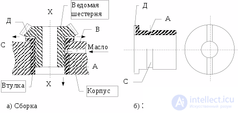
Fig. 9.6 Structural diagram of the operation of the bushing for the driven gear
To understand its functions, one must consider not only its functional components, but also the connections of the bushing with the supersystem, i.e., the housing into which it is installed, and the gear that it holds.
For a better understanding of the pattern of interrelation of the functions performed by the components of the technical system under consideration, the functional components are reflected in the model of function relations (Fig. 9.7).
It should be noted that not only parts but also assemblies, as well as individual structural elements of parts, can serve as functional components.
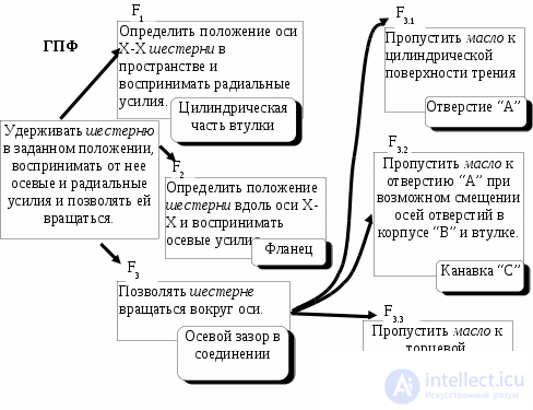
Fig. 9.7 Diagram of the interrelation of the functions of the bushing of the driven gear.
In order not to complicate the model shown in Fig. 9.7, the undesirable effects are compiled in Table 9.2.
For a detailed analysis of the functions, alongside the model in the form of a graph, it is advisable to develop a tabular model in which the level of performance of the functions and the UE are noted (Table 9.2). Another section can be introduced into the tabular model – measures for eliminating the UE.
Table 9.2 Tabular model for Example 9.1
|
Name of the function |
Name of the component |
Rank of the function |
Level of performance |
Undesirable effects |
|
F1. Determines the position of the X-X axis of the gear in space and absorbs radial forces. |
Inner cylindrical part |
Main. |
Excess. 1 |
Friction, uneven wear leads to an increase in the clearance in the gear joint. |
|
F1. Determines the position of the X-X axis of the bushing in space relative to the housing. |
Outer cylindrical part |
Main. |
Adeq. |
High accuracy of the diameter. High requirements for coaxiality with the inner cylindrical surface. |
|
F2. Determines the position of the gear along the X-X axis and absorbs axial forces |
Flange |
Main. |
Excess.2 Adeq. |
Friction; wear leads to an increase in the clearance in the gear joint. |
|
F3. Allows the gear to rotate about the axis. |
Inner cylindrical part |
Main. |
Adeq. |
The clearance in the joint leads to an additional clearance in the gear joint |
|
F31. Passes oil to the friction surface |
Hole “A” |
Main. (Req.) |
Insuff.3 |
The action is local, but it is needed over the entire friction surface. |
|
F32. Passes oil to hole “A” in case of a possible misalignment of the axes of the holes in the housing “B” and the bushing. |
Groove “C” |
Aux. (B1) |
Adeq. |
The strength of the bushing decreases, the hydraulic resistance increases. |
|
F33. Passes oil to the friction surface: flange of the bushing – flange of the gear |
Groove “D” |
Aux. (B1) |
Adeq.4 |
Increases the thickness of the flange3 |
Notes to Table 9.2:
1 – Two collars are sufficient for orienting the gear.
2 – Locating by a plane determines 3 coordinates, but only one is needed – the position along the X–X axis.
3 – The oil supply to the upper part can be enhanced by making spiral grooves on the cylindrical part of the gear.
4 – The function can be enhanced by using centrifugal forces, for example, by making a spiral groove on the end face of the gear adjacent to the bushing. The function can be enhanced by making a spiral groove on the cylindrical part of the gear.
It should be noted that measures 2 and 3 are oriented toward the use of supersystem resources.
The hierarchical model of function relations is convenient in that it allows one to see the interrelation of functions more clearly and, thereby, to clearly envision the consequences of possible directions for changing the TO with a view to improving it. From this diagram it is clearly seen that if a way is found to get rid of one of the main or auxiliary functions of a high rank, then the entire chain of functions to the right of the abolished function thereby disappears.
For example, a bushing made of a porous material will make it possible: not to make part of the structural elements of the bushing, to install the bushing itself in the housing on a thread, then it will become possible to adjust the clearance in the gear joint, both during initial assembly and as the end face of the gear or the bushing itself wears. Wear can be reduced through local hardening of the mating surfaces.
Thus, the hierarchical model is oriented toward the functional-value aspect of the analysis, in which such categories of thinking as the following are used: the function performed, undesirable effects, the system effect, and techniques aimed at increasing the degree of ideality of the TO (combination-separation, abolition of functions). All this activates thinking toward the search for other possible variants of solving the problem.
1.2.2. Subject-based approach
As has been noted, in the subject-based approach the vertices of the graph are occupied by structural components of the TO, which are identified from the technical system according to a functional characteristic (and not functions as in the hierarchical model, see Fig. 9.5).
When creating a TO of the second group (see p. Error: Reference source not found), a very important task is the formation of the physical operating principle of each converter. Therefore, for such TOs, a model proposed by A. I. Polovinkin Error: Reference source not found], which he called a flow functional diagram (FFD), can be very useful.
This model reflects the sequence of physical operations performed in transforming flows of substances, signals, and fields, and the temporal subordination of the functions (actions) being performed.
The generalized diagram of a TO consisting of a PE, Tr, CU, and WO, (Error: Reference source not found) can be regarded as an FFS, since it does not reflect the subordination, the hierarchy, of the functions.
A TS model in the form of an FFS also provides for an analysis of the adequacy of the functions performed and the use of techniques aimed at improving the technical object's performance of its MUF, proposed on p.12.
But, above all, this model focuses attention on which physical operation is performed by the functional component under consideration and which POP can implement that operation.
Example 9.2. The process of forming a hole using a pneumatic drill. Let us consider the FFS of the process of forming a hole using a pneumatic drill (Fig. 9 .8).
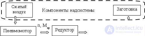
Fig. 9.8 Flow functional schema of the process of drilling a hole with a pneumatic drill
The heuristic usefulness of this model lies in the use of the operation of generalizing abstraction.
First, the functional components are identified for a specific object (prototype), and then an FFS is developed in the form of a graph. The vertices of the graph are the functional components, as well as the substances and fields that enter the input of the TO being analyzed. The arcs of the graph show the direction of the transformations of substances and fields. Phase variables can be indicated on them.
Then, for each functional component, the operation of generalizing abstraction is applied – a generalized name is given to the operation being performed (Fig. 9 .9).
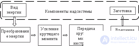
Fig. 9.9 Generalized flow functional schema of hole formation
Such a transition makes it possible to outline the choice of other physical operating principles for performing the physical operations.
For example, a different type of energy, a different gearbox layout, a different fixture for clamping the tool, and, finally, a different operating principle for the tool, for example, instead of cutting – punching a hole or applying electrophysical processes.
The transition from the specific FFS (Fig. 9 .8) to the generalized FFS (Fig. 9 .9) makes it possible to outline the field of possible solutions.
The use of a generalized name (Table 9 .3) helps to bring other POPs for the operation being performed into consideration, and activates thinking by drawing on analogies to search for possible technical solutions.
Table 9.3 Examples of applying the operation of generalization
|
Component |
Generalized name |
|
Spring, capacitor, compressed air |
Accumulator of potential energy |
|
Electric current voltage |
Type of energy of the control signal |
|
Thermometer, ammeter … |
Meter of a state parameter |
|
Milling cutter |
Tool, WO |
|
Transformer, gearbox |
Converter |
|
Stop, safety valve |
Limiter of the function performed |
|
C – L circuit |
Signal filter |
|
Electric motor, generator |
Converter of one type of energy into another |
For example, the term meter of a state parameter can lead to the idea of measuring a different parameter in order to organize a control or monitoring function. And the terms: type of energy of the control signal point toward searching for the possibility of using a different type of energy or control signal.
It should be noted that, unlike the hierarchical model, an FFS is simpler to analyze. It can be represented in the form of a linear graph or a linear graph with feedback loops.
In the process of designing a structure, an engineer solves a number of problems, as a result of which structural components are formed in the structure of the technical object. On the one hand, these components ensure the performance of the MUF that reflects the purpose of the TO. And, on the other hand, there are structural components that ensure the structural integrity of the object, the fulfillment of additional requirements specified in the design assignment, as well as those dictated by production and operating technology.
In general, in a TO one can distinguish structural components intended to perform the following functions (Fig. 9 .10):
main useful functions – determining the required mutual arrangement of the parts of the structure of the technical device and their connection to one another;
design functions – fulfillment of specified technical requirements;
technological functions – ensuring the manufacturability of the structure.
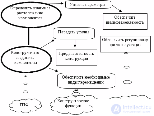
Fig. 9.10 Hierarchical model of the functions that ensure the structural integrity of a technical system.
To analyze the functions of the components that ensure the structural integrity of a technical device, A. I. Polovinkin Error: Reference source not found] proposed a model that he called the constructive functional schema (CFS).
In this model, the functional components of the technical device are placed at the vertices of the graph, and the edges reflect the structural connections between them. The logical basis for the decomposition of the TO is likewise the functional purpose of the parts being distinguished.
For static objects, these may be components whose functioning is aimed at performing the MUF. For technical objects that carry out the transformation of flows of energy and signals, the components that ensure the structural integrity of the technical object are distinguished. Here it is important to establish which functional components ensure the integrity of the structure of the technical system and how they are connected with one another.
The tabular model provides a description of the functions of the distinguished components and the connections between them, gives an assessment of the level at which the functions are performed, and considers possible options for design-and-technology solutions.
When formulating the functions of structural components, one should be guided by the recommendations set out in Section 1.1. However, it is not always possible to formulate a function according to the scheme:
< Action > <Object of the function > < Circumstances>.
Here the following formulations are possible: Is intended for …, Serves for ….
That is, a verbal-noun form is more often used here to describe the function (see Table 9 .1).
Example 9.3. Construction of the CFS of a transition truss. Transition trusses (Fig. 9 .11) are installed between the bays of an aircraft. They may house protruding parts of the propulsion unit, part of the bottom of the fuel tank, and elements for stage separation.
The main useful function of a transition truss is: determining the mutual position of the end frames and transmitting axial forces over a specified distance between two frames.
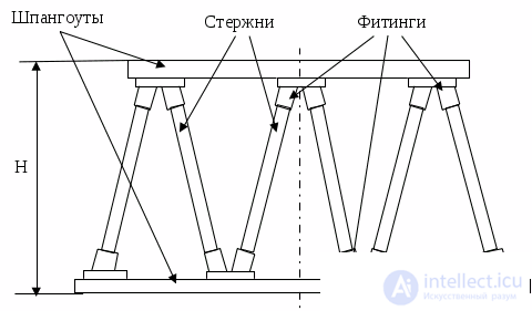
Fig. 9.11 Sketch of a transition truss
To carry out a functional analysis, a tabular model is drawn up (Table 9 .4) and a model of the connections of the structural elements in the form of a graph (Fig. 9 .12).
Table 9.4 Tabular model for the constructive functional schema of a transition truss
|
No. |
Functional component |
Function performed |
|
1 |
Frame |
1. Determining the position of the truss relative to the frame of the adjacent bay. 2. Absorbing the bending moment from external loads. 3. Giving the truss spatial rigidity. |
|
2 |
Rod |
Transmitting axial forces over a specified distance. |
|
3 |
Fittings |
1. Transmitting and distributing axial loads from the rod to the frame. 2. Determining the position of the rods relative to one another and to the frame. 3. Ensuring the possibility of automatic welding of the fitting to the rods. |
The working organ in this technical system is the rods – it is they that perform the MUF. The remaining components perform auxiliary and additional functions.

Fig. 9.12 Structural schema of the truss
To assess the level at which the functions are performed, it is necessary to analyze whether the material, shape, and dimensions selected for each component correspond to the level of the loads acting on it, and whether the types of joints have been chosen rationally.
In the example given, the main UE is the large number of elements and, accordingly, of joints. This leads to increased costs for their manufacture and assembly.
Attempts to improve the technical object may be aimed at changing its structure. Here one can outline the following measures for improving the design.
1. Structurally combine functional components or eliminate some of them, transferring their function to another component. For example, eliminate the fittings, transferring their function to the frame, i.e., combine the fitting with the frame, or transfer their function to the rod.
2. Transfer some functions to the supersystem. For example, eliminate a frame – do not make one of the frames, i.e., the truss is joined to the adjacent bay via the fittings.
3. Change the connections between the components, i.e., consider other possible types of joints.
Example 9.4 Check valve. Check valves are widely used in the pneumatic and hydraulic systems of aircraft, as well as in household equipment, for example, in gas cylinders for filling them.
The MUF of a check valve: to let the working medium pass from cavity A to cavity B when the pressure in cavity A rises, and not to let it pass in the reverse direction when the pressure in cavity B rises (Fig. 9 .13).
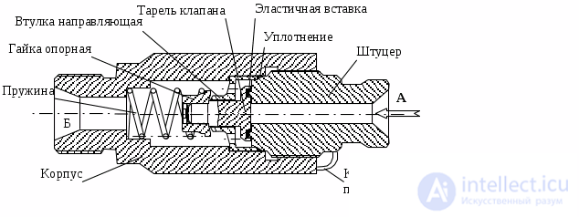
Fig. 9.13 Sketch of a check valve
To carry out a functional analysis, Table 9 .5 is drawn up.
Table 9.5 Tabular model of a check valve
|
Item |
Component name |
Function |
Undesirable effects |
|
Description |
|||
|
1 |
Body |
Determines the position of the fitting and the spring. Connects the valve to the piping |
|
|
2 |
Spring |
Moves the valve and presses it against the seat |
In the “Open” position it creates hydraulic resistance |
|
3 |
Support nut |
Transmits force from the spring to the valve Guides the spring |
|
|
4 |
Guide bushing |
Guides the movement of the valve in the body |
The moving joint operates in the working medium, high precision of fit is required, and wear debris clogs the piping. |
|
5 |
Valve disc |
Opens the line when pressure rises in the inlet cavity and closes it in all other cases |
|
|
6 |
Elastic insert |
Seals the disc-to-fitting joint |
|
|
7 |
Seal |
Seals the threaded joint |
|
|
8 |
Fitting |
Connects the valve to the inlet piping |
|
|
9 |
Locking wire |
Prevents the fitting from unscrewing spontaneously from the body |
It should be noted that some of the listed functional components ensure the structural integrity of the valve, while some perform the MUF. But these functional components are structurally connected with those that ensure the integrity of the system.
The CFS in the form of a graph (Fig. 9 .14) reflects only the structural connections.
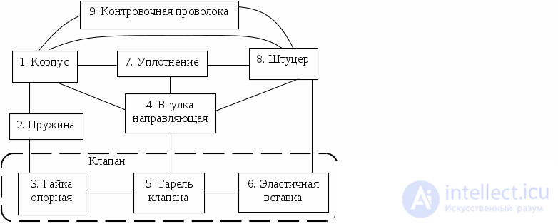
Fig. 9.14 Constructive functional schema of a check valve
The structural connections in the constructive functional schema are bidirectional, so the CFS graph is undirected (unlike the hierarchical model and the FFS). In most cases the constructive functional schema has a network structure. From the schema (Fig. 9 .14) it can be seen that the number of connections in the CFS is significantly greater than the number of components. And while for simple objects this may not be so important, when analyzing technical systems that have a large number of components, the resulting model becomes cumbersome, hard to survey, and difficult to analyze.
In this case, several components can be combined into a single functional group. That is, a hierarchical approach can be applied to modeling the structural connections.
The CFS directs attention to the choice of design-and-technology solutions (DTS) for parts and assemblies: materials, shape, the mutual arrangement of structural elements, and types of joints.
The types and number of joints significantly affect the labor intensity of the assembly processes and production costs. Mating surfaces, as a rule, are subject to higher requirements for manufacturing precision than other surfaces.
In the example considered, the following techniques can be applied to improve the design: removal, combination, and separation of structural elements.
For example, in the valve (Fig. 9 .13) the following changes can be considered:
1. Eliminate the guide bushing, transferring its functions to the body.
2. Move the elastic insert from the fitting to the valve disc.
3. Eliminate the support nut, transferring its functions to the disc, and so on.
It must be remembered that any change in the design of a TO, even a very minor one, leads to a change in the system properties, which can manifest themselves either favorably or unfavorably.
The interrelationship of the functions of a check valve in the form of an Ishikawa diagram is shown in Fig. 9 .15. Its MUF consists of two functions that must be performed at different points in time.
The working organ in this device, which performs the MUF, is represented as the interaction of two components: the disc and the fitting.
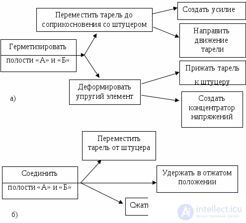
Fig. 9.15 Schema of the interrelationship of the main functions of a check valve (hierarchical model)
Comparing the schemas in Fig. 9 .15 and Fig. 9 .14, it can be seen that the hierarchical model of function connections is simpler than the CFS, since it contains no structural elements.
The components of a hierarchical functional schema are the functions performed, while the arcs reflect the connections and subordination of the functions. In a CFS the components are the functional components of the TO. And the edges reflect the structural connections – the joints between the functional components.
Example 9.5. Machine-tool fixture. Let us consider the generalized schema of a machine-tool fixture that can be mounted on both drilling and milling machines (Fig. 9 .16).
The MUF is to determine the position of the workpiece relative to the tool and to maintain this position under the force exerted by the tool on the workpiece (Table 9 .6). It should be noted here that the second function is subordinate to the first.
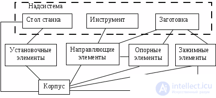
Fig. 9.16 Constructive functional schema of a machine-tool fixture
Table 9.6 Description of the functions of the components of a machine-tool fixture
|
Component name |
Functions performed |
|
Locating |
Determine the position of the body relative to the machine table. |
|
Guiding |
Determine the position of the tool relative to the support elements. |
|
Support |
Determine the position of the workpiece relative to the guiding and locating elements. |
|
Clamping |
Transmit the clamping force to the workpiece. |
|
Drive |
Create the clamping force. |
|
Body |
Determines the mutual position of all structural elements relative to one another and their position on the machine table and relative to the tool. |
The hierarchical model (Fig. 9 .17) makes it possible to identify the main, auxiliary, and additional functions that must be provided for so that the MUF is performed.
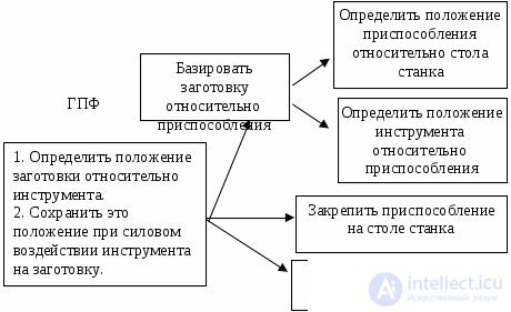
Fig. 9.17 Interrelationship of the functions performed by a machine-tool fixture (hierarchical model)
Isolating the functions allows one to bring in the operation of isolating abstraction (see Error: Reference source not found) to search for undesirable effects.
For example, the following UEs from the clamping force can be noted.
1. Deformation of the workpiece from the clamping force and the cutting forces.
2. Formation of dents on the workpiece from the parts in contact with it: the support and clamping elements.
Continuation of Example 9 .2. Fig. 9 .8 showed the FFS of the process of drilling a hole with a pneumatic drill. Fig. 9 .18 and Fig. 9 .19 show, for comparison, the hierarchical functional model of an electric drill and its CFS.
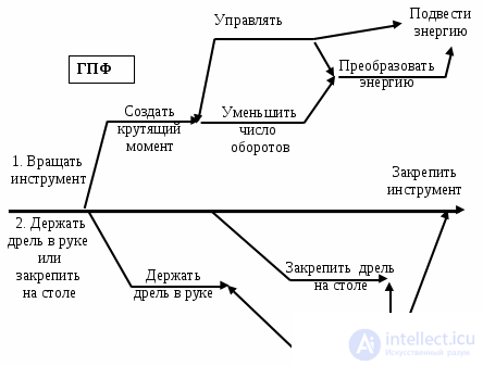
Fig. 9.18 Hierarchical functional model of an electric drill
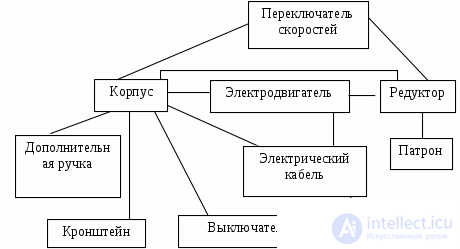
Fig. 9.19 Constructive functional schema of an electric drill
In conclusion, it should be noted that functional analysis and the models used in it are one of the initial stages of solving a technical problem. It is intended, first of all, to clearly formulate the problems that need to be solved and allows one to conceptually decide on the directions for searching for solutions.
The hierarchical model (Fig. 9 .3) is the most general and universal. It can be used to analyze any systems.
For technical objects that carry out the transformation of flows of energy and signals, it is convenient to use an FFS. This model orients one toward the search for PTEs and the synthesis of POPs of the distinguished functional components, and corresponds to a greater degree to an operational way of thinking.
People with an object-oriented style of thinking are inclined toward constructing a CFS. However, the use of this model does not exclude carrying out an operational analysis of the structure of the TO under consideration as well.
When solving a problem, one must strive to find models that allow a deeper understanding of the problem and help in the search for a solution. When choosing a model, one must clearly realize that the model must be easy to survey, instrumental, and must activate thinking. Therefore, the choice of a model is linked both to the features of the TO being studied, the type of its functioning, and to the priority type of thinking of the person solving the problem (see Error: Reference source not found).
← back

Comments