
Lecture
The architectural framework
Every software system must have a simple and at the same time all-encompassing organizing philosophy. The weather monitoring system is no exception in this respect. At the next stage of our work we must clearly define the architecture of the project. This will give us a stable foundation on which we will build the individual functional parts of the system.
There are a whole range of architectural models for solving problems of data acquisition, processing, and control, but the most frequently encountered are the synchronization of autonomous actors and the frame-by-frame processing scheme.
In the first case the system architecture is composed of a number of relatively independent objects, each of which executes as a thread of control. We could, for example, create several new sensor objects, built with the help of more primitive abstractions, each of which would be responsible for reading information from a particular sensor and for passing it to a central agent that processes all the information. Such an architecture has its advantages and is, perhaps, the only acceptable model in the case of designing a distributed system that must process a large number of parameters arriving from remote sensors. This model also allows the data acquisition process to be optimized more effectively (each sensor object can contain within itself information about how it should adapt to changes in the surrounding conditions - increasing or decreasing the polling rate, for example).
However, such architectures turn out not always to be acceptable when building hard real-time systems, where predictability of the processing must be guaranteed. The weather monitoring station cannot be classified as such a system, but nevertheless a certain degree of predictability and reliability is required of it. For this reason we choose the frame-by-frame processing model for our system.
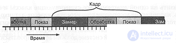
Figure 8-12. Frame-by-frame processing.
As shown in Figure 8-12, the monitoring process is carried out in this case as a sequence of readings, processing, and display of the parameter values at definite intervals of time. Each element of such a sequence is called a frame; it, in turn, can be broken down into a number of subframes corresponding to particular functional behavior. Different frames may carry information about different parameters. Wind direction, for example, must be measured every 10 frames, while wind speed - every 30 frames [For example, if frames are read every 1/60 of a second, then 30 frames occupy 0.5 second]. The main advantage of such a model consists in the fact that we can more strictly control the sequence of the system's actions for collecting and processing information.
Figure 8-13 shows a class diagram reflecting the features of the system's architecture. Here we have, in the main, the same classes that were identified at the analysis stage. The chief difference from the previous diagrams consists in the fact that we now see in what way the key abstractions of our software application interact with one another. We naturally cannot show on a single diagram all the existing classes and the relationships among them. Here, for example, the hierarchy of sensor classes is not reproduced.
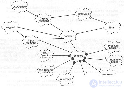
Figure 8-13. The architecture of the weather monitoring system.
In addition, we have introduced one new class, Sensors, which serves to gather all the sensor objects into a collection. Since at least two agents (Sampler and InputManager) in our system must be associated with a whole collection of sensors, placing them in a single container class allows all the sensors to be treated in a uniform manner.
The frame-by-frame processing mechanism
The behavior of our system is mainly determined by the interaction of the classes Sampler and Timer, and therefore, in order to justify our model, we should be especially careful in describing them.
Let us begin by developing the external interface for the class Timer, which dispatches the callback function (all decisions will subsequently be implemented in the C++ language). First, using the typedef keyword, let us define a new variable type, Tick, corresponding to the vocabulary of our problem domain.
// A time interval measured in 1/60ths of a second
typedef unsigned int Tick
Then let us define the class Timer:
class Timer {
public:
static setCallback(void (*)(Tick));
static startTiming();
static Tick numberOfTicks();
private:
...
};
This is an unusual class, if only because it contains rather unusual information. The member function setCallback is used to pass the callback function to the timer. The timer is started by a call to the startTiming function, after which the single instance of the class Timer begins to invoke the callback function every 1/60 of a second. Note that the start-up function is introduced explicitly, since one cannot rely on how a particular implementation determines the order in which declarations are processed.
Before moving on to the class Sampler, it is desirable to introduce an enumerated type of all the sensors present in our system, as follows:
// Enumeration of the sensor names
enum SensorName {Direction, Speed, WindChill, Temperature, DewPoint, Humidity, Pressure};
Now we can define the interface of the Sampler class:
class Sampler {
public:
Sampler();
~Sampler();
void setSamplingRate(SensorName, Tick);
void sample(Tick);
Tick samplingRate() const;
protected:
...
};
So that a client can dynamically change the sampler's behavior, we have defined the modifier setSamplingRate and the selector samplingRate.
To provide the connection between the classes Timer and Sampler, we will have to make a little more effort. In the following fragment of code an object of the class Sampler is created and a "non-class" function acquire is defined:
Sampler sampler;
void acquire(Tick t)
{
sampler.sample(t);
}
After this we can write the main function, which simply attaches the callback function to the timer and starts the sensor polling process:
main() {
Timer::setCallback(acquire);
Timer::startTiming();
while(1);
return 0;
}
This is a fairly typical main function for an object-oriented system: it is short (because the main work is delegated to objects) and it includes a dispatch loop (empty in our case, since there are no background processes).
Let us continue with our problem. Let us now define the external interface of the class Sensors (the sensors). We assume that various concrete sensor classes exist:
class Sensors : protected Collection {
public:
Sensors();
virtual ~Sensors();
void addSensor(const Sensor& SensorName, unsigned int id = 0);
unsigned int numberOfSensors() const;
unsigned int numberOfSensors(SensorName);
Sensor& sensor(SensorName, unsigned int id = 0);
protected:
};
This is essentially a collection class, and therefore it is declared a subclass of the foundation class Collection. The class Collection is specified as a protected superclass; this is done in order to hide the details of its structure from the clients of the class Sensor. Note that the set of operations we have defined for the class Sensors is extremely meager - this is caused by the limited nature of the class's tasks. We know, for example, that sensors may be added to the collection, but not removed from it.
Thus, we have devised a collection class for sensors that may contain many instances of sensors of one and the same type, with each instance of its class having a unique identification number, starting from zero.
Let us return to the specification of the class Sampler. We must provide for its association with the classes Sensors and DisplayManager:
class Sampler {
public:
Sampler(Sensors&, DisplayManager&) ;
protected:
Sensors& repSensors;
DisplayManager& repDisplayManager;
};
Now we must change the fragment of code where an instance is created of the class Sampler:
Sensors sensors;
DisplayManager display;
Sampler sampler(sensors, display);
When a Sampler object is created, a link is established between it, the sensors collection, and the instance of the class DisplayManager that will be used by the system.
Now we can take up the description of the key operation of the class Sampler, namely, sample:
void Sampler::sample(Tick t)
{
for (SensorName name = Direction; name <= Pressure; name++)for (unsigned int id = 0; id < repSensors.numberOfSensors(name); id++)if (!(t % samplingRate(name)))
repDisplayManager.display(repSensors.sensor(name, id).currentValue(), name, id);
}
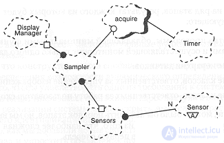
Figure 8-14. The frame-by-frame processing mechanism.
This function polls in turn each type of sensor and each sensor within a type. It checks whether it is time to read information from the sensor, and if so, obtains a reference to the sensor in the collection, reads its current value, and passes it to the display manager associated with the given instance of the class Sampler.
The semantics of this operation is based on the polymorphic behavior of a particular method, namely:
virtual float currentValue();
defined for the base class sensor. This operation is also based on the display function of the class DisplayManager:
void display(float, SensorName, unsigned int id = 0);
Now, after we have refined this element of our architecture, we can draw up a new class diagram reflecting the frame-by-frame processing mechanism (Figure 8-14).

Comments