
Lecture
Essentials: modules and their dependencies
A module diagram shows the allocation of classes and objects to modules in the physical design of the system. Each individual module diagram represents some view of the module structure of the system. During development we use the module diagram to show the physical division of our architecture into layers and partitions.
Some languages, Smalltalk above all, have nothing resembling a physical architecture formed by modules; in such cases module diagrams are not used.
The main elements of a module diagram are modules and their dependencies.
Modules. Fig. 5-32 summarizes the notation for the various types of modules. The first three icons are files, differing in their functions. The main program icon denotes a file containing the root program. In C++, for example, this would correspond to some file with the extension .cpp containing a privileged nonmember function called main. Usually there is exactly one such module per program. The specification icon and the body icon denote files that contain, respectively, declarations and implementations. In C++, for example, a specification module corresponds to a header file with the extension .h, and a body module to a file with program text with the extension .cpp.
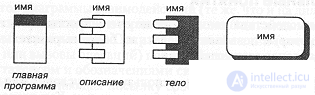
Fig. 5-32. Icons for modules and subsystems.
The meaning of the subsystem icon will be revealed in the next section. Every module must have a name; usually this is the name of the corresponding physical file in the project directory. As a rule, such names are written without suffixes, which are recognized from the type of the icon. If a name is too long, we, as usual, either shorten it or enlarge the icon. Every full file name must be unique within the subsystem containing it. In accordance with the rules of the particular development environment, we may impose constraints on names, such as a condition on prefixes or a requirement of uniqueness within the system.
Every module contains either the declaration or the definition of classes and objects, as well as other language constructs. Conceptually, by "opening" the module icon on the diagram, we should end up inside the corresponding file.
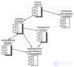
Fig. 5-33. Module diagram of the hydroponics system.
Dependencies. The only relationship that can exist between two modules - the compilation dependency - is represented by an arrow leading out of the dependent module. In C++, for example, we indicate such a dependency with the #include directive. Similarly, in Ada a compilation dependency is indicated by the with clause. No cycles may occur in the set of compilation dependencies. To determine a partial ordering of compilations, it is sufficient to carry out a partial ordering of the system's module structure.
Example. Fig. 5-33 shows an example of module notation in the architecture of the hydroponics greenhouse system. We see six modules here. Two of them, climatedefs and cropdefs, are specifications only and serve to provide common types and constants. The remaining four include both bodies and specifications: this is the typical style of building module diagrams, since specifications and bodies are very closely related. In the figure these two parts are combined, and the dependency of the body on the specification has turned out to be hidden, although in reality it exists. The name of the body has also turned out to be hidden, but, by our convention, the names of the body and the specification differ only in their suffixes (.cpp and .h).
The dependencies on this diagram imply a partial ordering of compilation. For example, the body of the module climate depends on the specification heater, which, in its turn, depends on the specification climatedefs.Essentials: subsystems. As was explained in Chapter 2, large systems may be decomposed into several hundred, if not thousand, modules. Trying to make sense of the physical architecture of such a system without additional structuring of it is almost hopeless. In practice developers tend to follow the informal convention of gathering related modules into directory-like structures. For these reasons we will introduce the concept of a subsystem on a module diagram. Subsystems constitute collections of logically related modules, much as a class category represents a collection of classes.
Subsystems. Subsystems serve as parts of the physical model of the system. A subsystem is an aggregate containing other modules and other subsystems. Every module in the system must live in one subsystem or reside at the very top level.
Fig. 5-32 shows the notation for a subsystem. Like a module, a subsystem must be named. The names of subsystems obey the same rules as the names of modules, although the full name of a subsystem usually contains no suffixes.
Some modules contained in a subsystem may be public, that is, exported from the system and visible from outside. Other modules may be part of the subsystem's implementation and not intended for use by external modules. By convention, every module of a subsystem is considered public unless explicitly stated otherwise. Restricting access to implementation modules is achieved using the same notation as for restricting access in class categories.
A subsystem may depend on other subsystems and modules; a module may also depend on a subsystem. For uniformity we use the same notation for dependency as before. The system has one top level, consisting of the subsystems and modules of the highest level of abstraction. From its diagram the developer gains an idea of the overall physical architecture of the system.
Example. Fig. 5-34 shows the top level of the module diagram for our greenhouse system. Opening any of the seven subsystems shown, we will discover all of its modules.
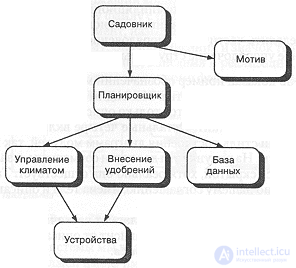
Fig. 5-34. Top-level module diagram for the hydroponics system.
Let us consider how the physical and logical (Fig. 5-7) architectures of this system are related. They are practically isomorphic, although there are small differences. In particular, we made the decision to separate the low-level device classes from the class categories Climate and Fertilizers, and to place the modules corresponding to them in a single subsystem called Devices. In addition, we split the class category Greenhouse into two subsystems, called ClimateControl and FertilizerApplication.
Advanced concepts
Other types of modules. Some languages, Ada first of all, define types of modules other than the simplest ones shown in Fig. 5-32. For example, Ada provides for generic packages, generic subprograms and tasks as separately compilable units. There are therefore grounds for supplementing the basic notation with icons for the module types specific to a given language.
Segmentation. For platforms that have limitations on addressing or on physical memory, a decision may be made to generate code in different segments, or even to organize an overlay structure. To reflect such segmentation, the module diagram notation can be supplemented by furnishing each module with a label denoting the corresponding code or data segment.
Specifications. Just as with class and object diagrams, every element of a module diagram may have a specification that defines it completely. The specifications of modules and their dependencies contain only the information already described in this section, so we will not consider them.
In an integrated tool environment supporting our notation, it is reasonable to use module diagrams to visualize the software modules of the system. "Opening" a module or subsystem on a module diagram opens the corresponding physical file or directory, and vice versa.

Comments