
Lecture
The software industry has developed to such an extent that it now encompasses many new application areas: from embedded microcomputers for controlling an automobile engine to performing routine work in the making of films and providing interactive access for millions of television viewers to video information databases. A distinguishing feature of such large systems is their extreme complexity. Of course, building a compact implementation of a system is an honorable task, but some large problems undoubtedly require a large volume of code. Large projects not infrequently involve programming organizations of hundreds of people, who must write millions of lines of code. Programs must satisfy requirements that inevitably change in the course of the work. As a rule, within the framework of such projects it is not a single program running on a single computer that is created, but a complex of programs functioning in a parallel distributed environment on several computers interconnected by a variety of information transmission channels. In order to reduce the probability of failure, such projects usually provide for a central organization responsible for the architecture and integrity of the system. Some parts of the system are not infrequently carried out under subcontract by other companies. Thus the development team never gathers together; it is distributed in space and - since in large projects there is constant turnover of personnel - in time as well.
If a developer who has been engaged in writing small, single-user programs in a windowing environment takes on the creation of a large system, he will undoubtedly be frightened by the problems that arise; possibly even to the extent that he will consider it folly to attempt to create such a program. But the reality is that large systems have to be built. And in some cases it is folly not to attempt it. Let us imagine manual control of air traffic around a capital city's airport, a life-support system for a space station dependent on the "human factor", or the keeping of accounts in an international bank performed on an abacus. The successful automation of such systems leads not only to the solution of the obvious problems, but also brings a multitude of unexpected benefits: a reduction in operating costs, an increase in reliability, an increase in functional capabilities. Of course, the key word here is successful. From all that has been said it is clear that the creation of large systems is an extremely difficult task. Therefore, in solving it, one must apply all the best of engineering practice and make use of the intuition of the leading designers.
This chapter presents just such a problem. It demonstrates how object-oriented design eases the carrying out of very large software projects.
12.1. Analysis
Defining the boundaries of the problem domain
For most people living in the USA, trains are a symbol of a long-departed era. In Europe and the countries of the East the situation is exactly the opposite. Unlike the USA, in Europe there are few national and international automobile highways, and the prices of petrol and gas are comparatively high. Therefore trains form the basis of the continent's transport network; over tens of thousands of kilometers of track a multitude of people and goods are carried every day - both within individual cities and between different countries. In fairness let us note that in the USA trains still play an important role in the transport of freight. As cities grow, their centers become more and more congested, and hopes are placed on light rail transport to solve the problem of congestion and of the pollution of the environment by internal combustion engines.
Railways are still commercial and consequently they must be profitable. Railway companies are obliged constantly to maintain a balance between the demands of economy and safety and the growing intensity of traffic on the one hand and an efficient and predictable schedule on the other. These contradictions suggest that decisions about controlling the movement of trains must be made automatically, and that this includes monitoring all elements of the railway by means of a computer.
Such automatic and semi-automatic systems exist today in Sweden, Great Britain, Germany, France and Japan . A similar system, called the Advanced Train Control System, was developed in Canada and the USA with the participation of the following companies: Amtrak, Burlington, Canadian National Railway Company, CP Rail, CSX Transportation, Norfolk and Western Railway Company, Southern Railway Company, Union Pacific. The effect of each of these systems has been both economic and social; the result of their introduction has been a reduction in operating costs, an increase in the efficiency of resource use, and safety.
Requirements for the traffic management system
The traffic management system performs two main functions: selecting routes for rail transport and monitoring the systems that support transport. These functions include: planning the transport, monitoring the location of trains, monitoring the transport itself, preventing conflicts, forecasting disruptions, and recording all operations. Figure 12-1 shows a schematic of the main elements of the traffic management system .
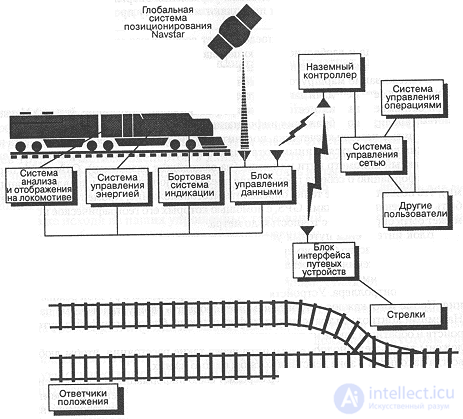
Figure 12-1. Traffic management system
The locomotive analysis and reporting system consists of a multitude of discrete and analog sensors for monitoring such parameters as temperature, oil pressure, fuel quantity, generator voltage and current, engine shaft revolutions per minute, water temperature, and tractive power. The values of the parameters from the sensors are conveyed to the engineer through a display system, and to the dispatcher and the maintenance personnel outside the train through a network. A warning or alarm signal is issued and recorded whenever a sensor reading goes outside the limits of the normal regime. The log of sensor readings is used in carrying out maintenance work and for managing fuel consumption.
The real-time energy management system prompts the train's engineer on how to make the most efficient use of the plant. The input data for this system are: the profile and condition of the track, speed restrictions, the schedule, the loading of the train, and the maximum power that can be developed. Proceeding from these data, the system can determine the operating regime of the propulsion plant that is optimal in terms of fuel consumption and consistent with the given schedule and the safety requirements. The system's recommendations, the profile and condition of the track, and the location and speed of the train can be displayed by means of the onboard display system.
The onboard display system provides the man-machine interface for the engineer. Information from the locomotive analysis and reporting system, the energy management system and the data management unit can be output to it. Special keys allow the engineer to view various data.
The data management unit constitutes a gateway between all the onboard systems of the train and the wide-area data transmission network to which all trains, dispatchers and other users are connected.
Tracking of the routes of train movement is carried out by means of location transponders connected to the data transmission network and the Navstar global satellite positioning system (GPS, Global Positioning System). The locomotive analysis and reporting system can compute the distance traveled by means of a counter that counts the number of wheel revolutions. This information is supplemented by data from location transponders, which are placed every kilometer of track or more often (at the most important junctions). The transponders transmit information about themselves to passing trains (using the data management unit), which makes it possible to determine the location more precisely. In addition, a train may be equipped with GPS receivers, by means of which its geographical position can be determined to within a meter.
The wayside interface unit is placed wherever there is some controllable device (for example, a switch) or a sensor (for example, an infrared sensor for detecting overheating of the wheel suspensions). Each interface unit receives commands (for example, commands to turn a signal on and off) from a local ground-based controller. Devices can be switched to manual control mode. In addition, each device can report its setting parameters. The ground-based controller relays information to and from the wayside interface units, and also to and from trains passing by. The controllers are located along the railway track at such distances that any train is always within range of at least one of them.
Each ground controller passes its information on to a unified network control system. Communication between the network control system and a ground controller may be carried out by microwave radio, by landlines, or by fiber optics, depending on how remote the given controller is. The network control system keeps the entire network running. It can automatically reroute information over a different path in the network if an equipment failure occurs along one of the routes,
The network control system, in turn, connects to one or more dispatch centers, which together make up the operations control system. The network control system is also connected to other users. Within the operations control system, dispatchers can set train routes and track train movement. Individual dispatchers are assigned to control different territories; each dispatcher control console is responsible for one or more territories. Routing trains means issuing instructions to automatically switch a train from one track to another, setting speed limits, controlling the passage of automobiles at crossings, and permitting or prohibiting train movement depending on whether particular sections of track are occupied. Dispatchers can observe the state of the track ahead along a train's route and relay that information to the engineer. Trains can be stopped by the operations control system (manually by dispatchers or automatically) when a hazard is detected (a train falling behind schedule, track damage, the possibility of a collision). Dispatchers can also call up on screen any information available to the engineers of individual trains, distribute train orders, set the parameters of wayside devices, and revise the movement plan.
Track layout and wayside equipment may change over time. The number of trains and their routes may change daily. The system must make it possible to connect new sensors, networks, and equipment built with more advanced technologies.
The sidebar states the basic requirements for the train traffic management system. Obviously, they are greatly simplified. In practice, the detailed requirements for a large system are worked out after the viability of a software solution to the problem has been demonstrated. The analysis then takes hundreds of person-months of labor involving experts in the given domain and users of the system. Ultimately, the requirements for the system may consist of thousands of pages of documentation specifying not only the basic behavior but also such details as the layouts of interface forms.
Even proceeding from our simplified requirements, however, we can make two observations about developing a traffic management system:
Our experience developing large systems shows that the initial statement of requirements is never complete; it is always to some degree indefinite and contradictory. Accordingly, we must be prepared to manage the uncertainties that arise during development. We strongly recommend evolving such systems as an incremental, iterative process. As was already said in Chapter 7, it is the development cycle itself that gives users and developers the opportunity to understand which requirements are actually essential; it is the development process, not exercises in the fine penmanship of specifications in the absence of a finished partial implementation or a prototype. In addition, one must take into account that building a large system may take several years. Over that time the hardware will change substantially [In fact, many systems of this level of complexity are characterized by the inclusion of computers of the most varied kinds. A well-thought-out and stable architecture mitigates the risk of a change of hardware during development, which happens all the time in the fast-changing computer world. New models come and go, so it is important to have a clear picture of the boundary between hardware and software, so that new computers or controllers that cut costs or improve performance can be introduced into the system while preserving the integrity of the architecture]. For this reason the requirements for the software must provide for adaptation to new hardware. There is no sense in creating an elegant architecture for hardware that is guaranteed to become obsolete during development. We believe that a software system's architecture should incorporate only those hardware features that rest directly on existing standards: communications, data networks, graphics, and sensor protocols. For entirely new systems one must sometimes become a pioneer in both hardware and software. This raises the risk, which for most systems is already high. Software development, especially when it comes to successfully completing a large application, inevitably involves risk, and our goal is to reduce that risk to a minimum.
Clearly we cannot examine every question of analysis and design for the system described in a single chapter, or even in a single book. Since our task is to show how the notation and methodology work, we will concentrate on building a flexible architecture for the domain under study.
System and software requirements: a fragile compromise
Large projects such as the one under consideration are usually organized around a small central group responsible for the global architecture of the system, while development itself is handed off to outside subcontractors or to other groups within the same organization. Already at the analysis stage the system architects have some conceptual model that separates the hardware and software parts of the implementation. Many, it is true, hold that this is no longer analysis but design. That is a debatable question. Indeed, it is hard to decide whether the diagram in Figure 12-1 shows the original requirements or the design of the system. In any case, though, the diagram implies that at this stage of development the architecture of the system is fundamentally object-oriented. For example, the diagram contains such complex objects as the energy management system and the operations control system. Each of them carries out one of the principal functions of the whole system. This is exactly what was discussed in Chapter 4: objects at the highest level of abstraction are responsible for the principal functions of the system. The process of analysis in this case therefore differs little from the process of design.
Once we have a skeleton of the architecture (as in Figure 12-1), we can, with the help of experts in the given application domain, begin developing the principal scenarios of system behavior, as was described in Chapter 6. To describe the expected behavior of the system in more detail, we can use interaction diagrams, object diagrams, action protocols, or prototypes. Figure 12-2 gives an interaction diagram of the system's components reflecting the scenario of preparing daily train movement orders. At this level of analysis we are interested precisely in the principal events and interactions that determine the behavior of the system. Such details as operation signatures and associations are tactical particulars that will be needed in later phases of design.
In a system of this size one can easily find hundreds of primary scenarios [We have encountered software system projects in which the results of analysis alone occupied more than 8,000 pages of documentation - an unmistakable sign of overly zealous analysis. A project that begins this way is rarely successful]. In Chapter 6 we already established the "80% rule." This means that before moving on to designing the architecture it is desirable to have captured 80% of the most important scenarios. Waiting for 100% completeness is pointless.
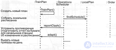
Figure 12-2. Preparing daily movement orders.
Clearly the system requirements must be translated into the language of requirements for its software and hardware parts, so that various competent organizations can work simultaneously on separate parts of the problem (but always under the supervision of some central group that maintains the overall vision of the project). Joint creation of hardware and software is a difficult task, especially if these parts are loosely coupled and are being created by different firms. Sometimes it is clear what hardware will be used. For example, off-the-shelf terminals or workstations can be used for the onboard display systems and in the operations control centers. Similarly, it seems entirely obvious that train scheduling is handled by software. The final decision about which basis, hardware or software, to use in each particular case depends on the developers' preferences as much as on anything else. Specialized hardware can be used when performance matters more, while using software is more sensible when flexibility must be provided.
Let us assume that an initial version of the hardware architecture has been chosen by the system architects. This choice must not be considered final, but at least it gives a point of departure for refining the software requirements. In the course of analysis, and then of design, we need the freedom to choose a hardware or a software implementation of one function or another: later it may turn out that additional hardware is needed, or that a given function can be implemented in software.
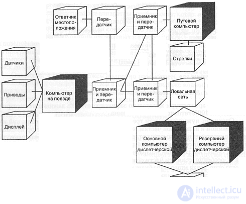
Figure 12-3. Process diagram of the traffic management system.
Figure 12-3 shows the target hardware for the traffic management system; our notation for process diagrams is used here. This process architecture corresponds to the diagram in Figure 12-1. In particular, one onboard computer is provided on each train, connecting the locomotive analysis and reporting system, the energy management system, the onboard display, and the data management device. We assume that certain onboard devices, such as the display, possess minimal intelligence, but that possibly not all of them are programmable. We assume that each transponder is connected to a transmitter that sends messages to a train passing by it; the computer is not connected to the location transponder. All groups of wayside devices (each of which logically consists of an interface and a switch) are controlled by a computer that can interact with a passing train or with a ground controller through their transmitters and receivers. Each ground controller is connected through a wide-area network to a dispatch center (which is part of the operations control system). To ensure uninterrupted service we decided to place two computers at each dispatch center: a primary and a backup (the second switches on in the event the primary computer fails). In its free time the backup computer can be used to serve other, low-priority users.
At the operational level the traffic management system may contain hundreds of computers: one for each train, one for each wayside device interface unit, and two for each dispatch center. The process diagram shows only some of the computers, since it is superfluous to show repeating components of the configuration.
As was already said in Chapters 6 and 7, common sense suggests that in developing a large project the sensibleness and clarity of the interfaces between the key parts of the system play an enormous role. This is especially important for the interface between the software and hardware parts of the system. At the beginning of work on the project the interface may not be fully defined, but it must be formalized quickly enough that the various parts of the system can be developed, tested, and integrated simultaneously. A well-defined interface makes it possible to assemble the system without substantial rework of its parts. In addition, we do not expect all the developers taking part in the project to be equally strong at programming. We must therefore entrust the specification of the key abstractions and mechanisms to the strongest system architects
Key abstractions and mechanisms
As a result of studying the requirements for the traffic management system it becomes obvious that we must solve four principal subproblems:
How did we conclude that it is precisely in these subproblems that the main development risk is concentrated?
The system is tied together by a distributed data transmission network. Messages are transmitted by radio: between transponders and trains, between trains and ground controllers, between trains and wayside device interface units, between ground controllers and wayside devices. In addition, messages must be transmitted between dispatch centers and individual ground controllers. Reliable operation of the whole system is ensured by the timely and reliable reception and transmission of messages.
In addition, the system must simultaneously store information about the location and planned routes of many trains. We must maintain constantly updated information and guarantee its integrity even in the event of attempts to write and read information simultaneously from different places in the network. Consequently, we need a distributed database.
Designing the human-machine interface poses yet another group of problems. The point is that the users of the system are mainly engineers and dispatchers, but none of them is required to possess professional computer skills. The user interface of operating systems such as UNIX or Windows is suitable (for the most part) for a professional programmer, but is considered far too hostile for the end users of environments such as the traffic management system. Consequently, all forms of interaction must be designed with this particular group of users in mind.
Finally, the traffic management system must interact with a variety of sensors and actuators. Without dwelling here on the nature of these devices, we note that the principles of controlling them do not depend on the specific type of device and should be chosen to be uniform throughout the system.
Each of these four subproblems comprises a whole series of distinct issues. The system architects must find the key abstractions and mechanisms of each problem, and then we will be able to bring in experts to solve each separate subproblem independently of the others. However, neither analysis nor design can be completed in a single pass - round after round, analysis will uncover new architectural problems whose solution will require new analysis. Development will thus inevitably be incremental and iterative.
From a brief problem analysis of the four main subproblems we see that there exist three high-level key abstractions:
| ® Trains | Locomotives and cars. |
| ® Tracks | The track profile, its quality, and wayside devices. |
| ® Plans | Schedules, orders, conflict resolution, assignment of authority, and crew selection. |
Each train is characterized by its current position on the tracks and may have only one active movement plan. Similarly, at each point of track there can be at most one train. Each plan pertains to only one train, but to many points of track.
We can single out a key mechanism for each of the four (nearly independent) subproblems:
These four mechanisms constitute the soul of our system. They are the most complex and riskiest parts of the project. It is important that we entrust the best system architects with experimenting with various approaches and gradually creating an environment on the basis of which more junior developers will do everything else.

Comments