
Lecture
Drawing diagrams is not yet analysis and not yet design. Diagrams make it possible to describe the behavior of a system (for analysis) or to show the details of its architecture (for design). If you observe an engineer at work (a programmer, a technologist, a chemist, an architect), you will quickly become convinced that the future system takes shape in the developer's mind and only there. When, after some time, the system becomes clear in general outline, it will most likely be represented on such high-technology media as notebook pages, napkins or old envelopes .
However, a well-thought-out and expressive notation is very important for development. First, a generally accepted notation allows a developer to describe a scenario or formulate an architecture and to set out his decisions intelligibly to his colleagues. The symbol for a transistor is understood by every electronics engineer in the world. Similarly, builders from San Francisco most likely will not have to puzzle for long over a design for an apartment building developed by architects in New York, deciding how the doors, windows or electrical wiring should be placed. Second, as Whitehead noted in his fundamental work on mathematics, "By relieving the brain of unnecessary work, a good notation sets it free to concentrate on more advanced problems" . Third, a clear notation makes it possible to automate most of the tedious checking for completeness and correctness. As the Defense Science Board report puts it:
"Software development will always be painstaking work... Although our machines can perform the routine work and help us keep the thread of our reasoning, the development of concepts will remain the prerogative of the human being... What will always be of value is the art of building a conceptual structure, while the cares of describing it will become a thing of the past" .
5.1. Elements of the notation
The need for different points of view
It is impossible to take in all the subtle details of a complex software system at a single glance. As Klein and Gingrich note: "It is necessary to understand both the functional and the structural properties of objects. One must also grasp the taxonomic structure of the classes of objects, the inheritance mechanisms used, the individual behavior of objects and the dynamic behavior of the system as a whole. This task is in some ways analogous to televising a football or tennis match, where several cameras placed at different corners of the sports ground are required in order to convey the action intelligibly. Each camera conveys its own aspect of the game, inaccessible to the other cameras" .
Fig. 5-1 presents the various types of models (described in Chapter 1) that we consider the principal ones in the object-oriented approach. It is through them that the results of the analysis and design carried out within any project will be expressed. Taken together, these models are semantically rich and universal enough for a developer to express all the noteworthy strategic and tactical decisions that he must make when analyzing a system and forming its architecture. In addition, these models are complete enough to serve as an engineering design for implementation in practically any object-oriented programming language.
Our notation is rich in detail, but this does not mean that every project must use all of its aspects. In practice, some small subset of this system is sufficient to describe most of the results of analysis and design; one colleague of ours calls such a lightened notation "the Booch Lite" notation (the abridged Booch notation). In the course of introducing our notation we shall clearly single out this subset. Why then bother with the details of the notation that are not included in the minimal subset? They are needed mainly to express certain important tactical decisions; and some of them are intended for the creation of CASE software tools. We shall call them supplements.
As Weinberg notes: "In some fields (such as architecture), in the process of design the graphical plan is most often presented in the form of general sketches, and strictly detailed descriptions are rarely used until the creative part of the design's formation is finished" . It should be remembered that a notation is only a means of expressing the results of reflection on the architecture and behavior of a system, and by no means an end in itself. One must use exclusively those elements of the notation that are necessary, and no more. Just as it is dangerous to impose requirements that are too rigid, it is not good to describe the solution of a problem in too much detail. For example, on a drawing an architect may show the location of a light switch in a room, but its exact place will not be determined until the client and the foreman inspect the already erected building to settle the details of the finishing. It would be foolish to indicate the three-dimensional coordinates of this switch on the drawing in advance (unless, of course, this is a functionally important detail for the client: perhaps all the members of his family are much taller or shorter than average). If the developers of a large software system are highly qualified specialists and have already learned to work together, rough sketches will be enough for them, although even in this case they must leave their creative legacy to the maintenance people in a palatable form. If, however, the developers are inexperienced, are separated from one another in time or space, or if this is stipulated by contract, then more detailed sketches of the design are needed throughout the whole design process. The notation we present in this chapter takes these situations into account.
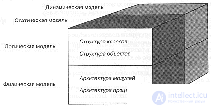
Fig. 5-1. Object models.
Different programming languages describe the same concepts differently. Our notation does not depend on any particular language. Of course, some of its elements may have no analogues in the language in which the system being designed will be written. In that case one simply need not use them. For example, in Smalltalk there are no free subprograms, and consequently there is no sense in building class utilities into the design. Similarly, C++ does not support metaclasses, and consequently this element must be excluded. But there is nothing reprehensible in adapting the notation to the constructs of the chosen language. For example, in CLOS operations can be furnished with special marks in order to define :before, :after and :around methods. In the same way, in a computer-aided design system for C++ one can use header files directly instead of class specifications.
The aim of this chapter is to define the syntax and semantics of our notation for object-oriented analysis and design. As an example we shall use the hydroponics greenhouse that was considered in Chapter 2. The present chapter does not discuss how, strictly speaking, the solutions presented in the examples were obtained: that is the task of Chapter 6. Chapter 7 discusses the practical aspects of this process, and in Chapters 8-12 the notation is demonstrated in action on a series of application development examples.
Models and views
In Chapter 3 we explained what classes and objects are, and also what the connection between them is. As shown in Fig. 5-1, in making decisions in analysis and design it is useful to consider the interaction of classes and objects in two dimensions: logical/physical and static/dynamic. Both of these aspects are necessary for determining the structure and behavior of an object system.
In each of the two dimensions we build several diagrams that give us a view of the system's models from various perspectives. Thus the models of a system contain all the information about its classes, relationships and other entities, while each diagram represents one of the projections of the model. When the design has settled into a steady state, all such diagrams must be consistent with the model and, consequently, with one another.
Consider, for example, a system that includes several hundred classes; these classes form part of the model. It is impossible, and in fact unnecessary, to represent all the classes and their relationships on a single diagram. Instead we can describe the model in several class diagrams, each of which represents only one of its perspectives. One diagram may show the inheritance structure of certain key classes; another the transitive closure of the set of all classes used by a particular class. When the model has "settled" (has come into a steady state), all such diagrams become semantically consistent with one another and with the model. For example, if in a given scenario (which we describe on an object diagram) object A sends message M to object B, then M must be directly or indirectly defined in class B. In the corresponding class diagram there must be an appropriate relationship between classes A and B, so that instances of class A really can send message M.
For simplicity, on the diagrams all entities with identical names in one scope are regarded as references to the same characters of the system. The only exception to this rule may be operations, whose names may be overloaded.
To distinguish among diagrams, we must give them names that reflect their subject and purpose. Diagrams may also be supplied with other comments or labels, which we will describe shortly; as a rule, these comments carry no additional semantics.
Logical and physical models
The logical view describes the set and the meaning of the key abstractions and mechanisms that shape the problem domain or define the architecture of the system. The physical model defines the concrete hardware and software platform on which the system is implemented.
During analysis we must ask the following questions:
As was noted in the previous chapter, we use scenarios to express our decisions about the behavior of the system. In the logical model, object diagrams serve as the most important means of describing scenarios. During analysis, class diagrams can be useful for seeing the common roles and responsibilities of objects.
During design we must ask the following questions about the architecture of the system:
To answer these questions, we use the following diagrams:
Static and dynamic models
The four kinds of diagram we have introduced are for the most part static. But in practically every system events take place: objects are created and destroyed, they send messages to one another in a definite order, and external events invoke the operations of objects. It is not surprising that describing dynamic events on a static medium, a sheet of paper for instance, is a difficult task, but this same difficulty is encountered in virtually every field of science. In object-oriented design we capture the dynamic semantics with two additional diagrams:
Each class may have its own state transition diagram, which shows how an object of the class moves from state to state under the influence of events. From an object diagram, given a scenario, one can build an interaction diagram in order to show the order in which messages are passed.
Design tools
A poor developer equipped with a computer-aided design system will simply be able to create his software monster in a shorter time than before. Great designs are produced by great designers, not by tools. Design tools give individuality a chance to show itself; they free it so that it can concentrate exclusively on the creative tasks of design and analysis. There are things that automated design systems can do well, and there are things they cannot do at all. For example, if we use an object diagram to show a scenario in which a message is sent from one object to another, an automated design system can guarantee that the message sent is part of the object's protocol; this is an example of a consistency check. If we introduce an invariant such as "there are at most three instances of this class," then we expect our tool to see that this requirement is observed; this is an example of a constraint check. In addition, the system can notify you if any declared classes or methods are not used in the design (a completeness check). Finally, a more sophisticated automated design system can determine the duration of a particular operation or the reachability of a state on a state diagram; this is an example of automated analysis. On the other hand, however, no automated system will be able to discover a new class that would simplify your class structure. We could, of course, try to build such a tool using expert systems, but that would require, first, experts both in object-oriented programming and in the problem domain, and second, clearly formulated rules of classification and a great deal of common sense. We do not expect such tools to appear in the near future. Meanwhile, we have perfectly real projects that are worth getting on with.

Comments