
Lecture
Modular architecture
We have already said that modularity is necessary for large systems but not sufficient; for problems on the scale of the traffic management system, one must concentrate on decomposition into subsystems. In the early stages of evolution we must develop a modular architecture for the system, representing the physical structure of its software.
The design of software for very large systems must begin before the design of the hardware is fully complete. Writing the software takes, as a rule, even more time than developing the hardware. In addition, as the process goes on, functionality may be redistributed between the hardware and software parts. Hardware dependencies must therefore be isolated as much as possible, so that software design can begin without being tied to the hardware. This also means that development must be based on the idea of interchangeable subsystems. In command and control systems such as the traffic management system, it is necessary to preserve the ability to take advantage of new hardware solutions that may appear during software development.
In the early stages we must sensibly carry out a decomposition of the software so that the subcontractors responsible for the various parts of the system can work simultaneously (possibly even using different programming languages). As was already said in Chapter 7, there are many nontechnical reasons that determine the physical decomposition of large systems. Most important is the question of interaction among the various development groups. Relationships among subcontractors are usually formed at fairly early stages in the life of a system, often before enough information has been obtained to choose the correct decomposition of the system.
It is desirable for the system architects to experiment with several alternative decompositions into subsystems in order to be confident of the correctness of the global decision on the physical design. Prototyping on a large scale can be employed, with simulation of subsystems and modeling of processor load, message routing, and external events. Prototyping and modeling can serve as a foundation for top-down testing as the system is built.
How does one choose a suitable decomposition into subsystems? In Chapter 4 it was noted that objects at a high level of abstraction are usually grouped according to their functional behavior. Let us emphasize once more that this does not contradict the object model, since we do not rigidly tie the term functional to the notion of an algorithm. We speak of functionality as externally visible and testable behavior that arises as a result of the joint activity of objects. Thus the high-level abstractions and mechanisms discussed earlier are well suited to the role of subsystems. We can first posit the existence of such subsystems and develop their interfaces some time later.
The module diagram in Figure 12-9 presents the top-level design decisions for the modular architecture of the traffic management system. Each level here corresponds to one of the four subproblems identified earlier: the data transmission network, the database, real-time analog control devices, and the human/computer interface.
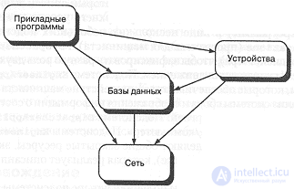
Figure 12-9. Top-level module diagram of the traffic management system.
Specifying the subsystems
If we examine the outside view of any of the subsystems, we discover that it possesses all the characteristics of an object. Each subsystem has a unique, albeit static, identity and a large number of possible states, and it also exhibits very complex behavior. Subsystems are used as repositories of other classes, class utilities, and objects; thus they are best characterized by the resources they export. In practice, when C++ is used, these resources take the form of directories containing logically related modules and nested subsystems.
The module diagram in Figure 12-9 is useful but not complete, since each of the subsystems shown on it is too large to be implemented by a single small team of developers. We must reveal the inside view of the top-level subsystems and carry out their decomposition.
Consider, for example, the subsystem NetworkFacilities (the network). We decided to break it into two other subsystems, one of which is private (RadioCommunication (radio communication)), and the other public (Messages (messages)). The private subsystem hides the details of its software control of physical devices, while the public subsystem provides support for the message passing mechanism designed earlier.
The subsystem named Databases (databases) is built on the basis of the resources of the subsystem NetworkFacilities and serves to implement the train movement plan mechanism we described above. We compose this subsystem out of two exported public subsystems, TrainPlanDatabase (the train plan database) and TrackDatabase (the track database). For actions common to these two subsystems we provide a private subsystem DatabaseManager (the database manager).
The subsystem Devices (devices) also naturally breaks down into several smaller subsystems. We decided to group the software relating to all wayside devices into one subsystem, and the software associated with the active mechanisms and sensors of the locomotive into another. These two subsystems are accessible to clients of the subsystem Devices, and both are built on the basis of the resources of the subsystems TrainPlanDatabase and Messages. Thus we have designed the subsystem Devices to implement the sensor mechanism described above.
Finally, we represent the top-level subsystem UserApplications (user applications) as several smaller subsystems, including EngineerApplications (engineer applications) and DispatcherApplications (dispatcher applications), in order to capture the different roles of the two main users of the traffic management system. The subsystem EngineerApplications contains the resources that provide for interaction between the engineer and the computer, in particular, analysis of the locomotive analysis and reporting system and of the energy management system. The subsystem DispatcherApplicatlona provides the dispatcher/computer interface. The subsystems EngineerApplications and DispatcherApplications share the common private resources exported from the subsystem Displays (displays), which implements the display mechanism described earlier.
As a result of design we have obtained four top-level subsystems and ten subsystems at the next level, in which all the key abstractions and mechanisms introduced earlier are housed. It is important that work can be planned and configurations and versions managed in terms of these subsystems. As was said in Chapter 7, one person can be responsible for each such subsystem, while a great many programmers will develop it. The person responsible for a subsystem elaborates its design and implementation and manages its interface with other subsystems at the same level of abstraction. Thus, by decomposing a complex problem into several simpler ones, it becomes possible to manage the development of complex projects.
In Chapter 7 the possibility of several simultaneous views of the system under development was already demonstrated. A set of compatible versions of subsystems forms a release, and there may be many such releases - one for each developer, another for testing, one for user trials, and so on. Individual designers can create their own stable releases for their own needs and integrate into them the parts for which they are responsible before handing them over to the others. This is how a mechanism of continuous integration of new code is created.
The basis of success is the careful construction of the subsystem interfaces. Once the interfaces have been defined, they must be carefully protected. How do we define the outside view of a subsystem? Each subsystem must be treated as an object. We therefore pose the same questions we asked in Chapter 4 for far simpler objects: What states does the object have? What actions can a client perform on it? What actions does it require of other objects?
For example, consider the subsystem TrainPlanDatabase. It is built on the basis of three other subsystems (Messages, TrainDatabase, TrackDatabase) and has several important clients - the subsystems WaysideDevices (wayside devices), LocomotiveDevices (locomotive devices), EngineerApplications and DispatcherApplications. The subsystem TrainPlanBatabase is relatively simple - it contains all the train plans. The trick, of course, is that this subsystem must support the mechanism for distributed transmission of train movement plans. From the outside the client sees a monolithic database, but from the inside we know that the database is in fact distributed, and we must therefore base it on the message passing mechanism of the subsystem Messages.
What actions can be performed with the help of TrainPlanDatabase? All the usual database operations: adding, deleting, and modifying records, and queries. Just as in Chapter 10, all the design decisions about this subsystem need to be captured in the form of C++ classes that will furnish us with declarations of operations.
At this stage we should continue the design process for each subsystem. Let us note once more that the likelihood that all the interfaces will turn out to be correct the first time is very small. Fortunately, as with small objects, experience suggests that most of the changes we make to the interfaces will not affect the upper levels (upward compatibility), provided we have done a good job of describing each subsystem in an object-oriented style.

Comments