
Lecture
As was already noted in Chapter 6, creating an architecture means identifying the basic structure of classes and specifying the common interactions that bring the classes to life. By concentrating our attention first and foremost on these mechanisms, we identify the elements of greatest risk from the very outset and direct all the system architects' efforts at them. The results of this phase provide a good foundation (in the form of classes and interactions) on which the functional elements of our system are built.
In this section we will examine in detail the semantics of each of the four key mechanisms identified.
The message passing mechanism
By a message here we do not mean the invocation of methods, as is customary in object-oriented programming languages. In this case the concept is taken from the vocabulary of the problem domain, from the highest level of abstraction. Here are several examples of messages in the traffic management system: a start signal to a wayside device, a report that a train has passed a particular point on the track, an order from a dispatcher to an engineer. All these kinds of messages can be transmitted within the traffic management system at two levels:
At present we are interested in the second level of message passing. Since the system includes a geographically distributed network, we must take into account such factors as interference, equipment failures, and the security of the information transmitted.
The first step in defining the messages in the system is to analyze the interaction of each pair of communicating computers (see Figure 12-3). For each such pair we must ask three questions: (1) What information does each computer process? (2) What information will be transmitted from one computer to the other? (3) At what level of abstraction will this information be? There is no empirical answer to these questions. We must proceed iteratively until we arrive at confidence that the right messages have been defined and that there are no bottlenecks in the communication system (which can arise from overloading of the communication lines or, for example, from a message being broken up into packets that are too small).
It is very important that at this stage of design attention be concentrated on the substance of messages, not on their form. All too often system architects begin design by choosing a bit-level representation for messages. In a real problem, a premature choice of a low-level representation will inevitably lead to changes later on and will affect everyone who used that representation. In addition, at an early stage of design we as yet have no complete information about how these messages will be used and, consequently, we cannot judge which representation will be optimal in size and transmission time.
Concentrating our attention on the substance of messages, we will consider all the classes of messages. In other words, we need to define the purpose and meaning of each message, and also to enumerate the operations for processing them.
The class diagram in Figure 12-4 shows some of the most important messages in the traffic management system. Note that all messages are ultimately instances of the abstract class Message, which encapsulates the behavior common to all messages. The three classes at the next level represent the main categories of messages: train status message, train movement plan message, wayside device message. Each of these three classes will be elaborated further. As a result of design, dozens of specialized classes should appear. The existence of generalizing abstract classes is thus extremely important; without them we would get hundreds of mutually unrelated and, consequently, hard-to-use modules, each of which would implement a specialized class. As design proceeds we will identify other important groups of messages and create specialized intermediate classes for them. Fortunately, changes in the class hierarchy need not trouble the clients that use the classes.
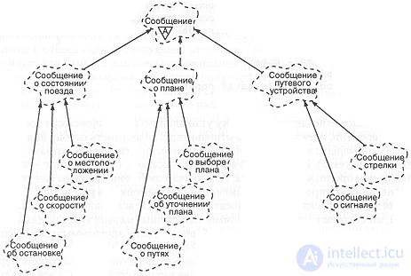
Figure 12-4. Class diagram of messages.
First of all we should stabilize the interfaces of the key message classes. It is best to begin this process with the base classes of the hierarchy. Let us begin by introducing the following two types;
//a number denoting the unique identifier of a packet
typedef unsigned int PacketId;
//a number denoting the unique network identifier
typedet unsigned Int NodeId;
Now let us give the definition of the abstract class Message:
class Message {
public:
Message();
Message(NodeId sender);
Message(const Message&);
virtual ~Message();
virtual Message& operator=(const Message&);
virtual Boolean operator==(const Message&);
Boolean operator!=(const Message&);
PacketId id() const;
Time timeStamp() const;
NodeId sender() const;
virtual Boolean isIntact() const = 0;
};
This class is responsible for setting the unique message identifier, the time stamp, the sender identifier, and the integrity of the message (namely, the class checks whether it is a syntactically and semantically legal message of the system). This last behavior shows that a message is something more than just a data record. As usual, messages must also provide operations for copying, renaming, and testing for equality.
When our design contains the interfaces of all the most important messages, we will be able to write programs based on these classes to simulate the creation and reception of message streams. Such programs can be used to test various parts of the system.
The class diagram in Figure 12-4 is unquestionably incomplete. In practice one must first develop the most important messages and add all the rest as less common forms of interaction are discovered. Using object-oriented design will allow us to add these messages incrementally without disrupting the existing parts of the system, since the possibility of change was taken into account from the very beginning.
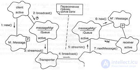
Figure 12-5. Message passing.
If we are satisfied with the class structure, we can begin designing the message passing mechanism itself. Two competing goals arise here: to devise a mechanism that will ensure reliable delivery of messages, but will do so at a sufficiently high level of abstraction that the client need not concern itself with how the message is delivered. Such a message passing mechanism will allow clients to make do with a simplified view of the transmission process.
Figure 12-5 shows the result of designing the message passing mechanism. As can be seen in the diagram, to send a message a client first creates a new message m, then passes it to the dispatcher of its own node, which queues the message for subsequent sending. Note that our design provides the client with the possibility of waiting if the node dispatcher cannot carry out the sending in time. The dispatcher receives the message as a parameter and then uses the services of a Transporter object, which provides the necessary message format and its distribution over the network.
We made this operation asynchronous so that the client does not wait while the message is sent by radio, which takes time for encoding, decoding, and retransmissions caused by interference. Ultimately a Listener object receives the message and converts it into the form accepted by the dispatcher of its own node, which creates a parallel message and queues it. The receiver may block on the head of the message queue, waiting for the arrival of the next message, which is passed as a parameter of the synchronous operation nextMessage.
In designing the dispatcher we place it at the application layer of the ISO OSI network model. This will allow all clients, transmitters, and receivers to work at the highest level of abstraction and to communicate with one another in terms specific to the given application.
We expect that the final implementation of the mechanism described will probably be somewhat more complex. For example, it may be necessary to encrypt and decrypt messages and to use error detection and correction codes in order to ensure reliable communication under conditions of interference on the communication lines and possible equipment failures.
Train schedule planning
We have already said that the concept of a train movement plan is central to the functioning of the traffic management system. Each train has one active plan, and each plan is intended for only one train. It may contain many different orders and points on the track.
Our first step consists in determining precisely what parts a train plan consists of. To do this we must enumerate all the potential clients of the plan and identify how each of them uses it. For example, some clients may be permitted to create plans, others to amend plans, and the rest will be able only to read plans. In this sense the plan acts as a repository of information associated with the route of one individual train and with the actions taken during movement. Examples of such actions might be detaching or attaching cars.
Figure 12-6 gives the strategic design decisions concerning the structure of the class TrainPlan. As in Chapter 10, we use a class diagram to show the parts of which a train movement plan consists (much as is done in traditional entity-relationship diagrams). We see that each plan contains one crew, but may include many orders and actions. We expect these actions to be ordered in time and that each action has associated information such as time, location, speed, responsible party, and orders. For example, a plan might contain the following actions:
| Time | Location | Speed | Responsible party | Order |
| 0800 | Pueblo | As directed | Yardmaster | Leave the yard |
| 1100 | Colorado Springs | 40 mph | Detach 30 cars | |
| 1300 | Denver | 40 mph | Detach 20 cars | |
| 1600 | Pueblo | As directed | Return to the yard |
From Figure 12-6 it can be seen that the class TrainPlan has one static object of type UniqueId, a so-called magic number that uniquely identifies each instance of the class TrainPlan.
As was done for the class Message and its subclasses, one can first design the most important elements of the train movement plan; the details will become clear as we use the plan for different clients.
The simultaneous existence of an enormous number of active and inactive train plans brings us back to the database problem we have already discussed. The class diagram in Figure 12-6 can serve as a sketch of the logical schema of this database. This raises the following question: where is a train plan stored?
In a perfect world, where there is no interference or delay in transmission and computer resources are unlimited, it would be best to place all train movement plans in a single central database. Such an approach ensures the existence of a single instance of each plan. Real conditions, however, make this solution inefficient: transmission delays are unavoidable, and processor performance is limited. Thus the speed of access from a train to a plan located at a dispatch center would not meet real-time requirements. With software, however, one can create the illusion of a centralized database. Our solution is that train plans will reside on the dispatch center computers, while copies of these plans will be distributed to the nodes of the network as needed. To ensure efficiency, each train's computer can store a copy of its own plan. The onboard software can thus obtain the information it needs with negligible delay. If a plan changes as a result of a dispatcher's actions or (less likely) by decision of the engineer, our software must guarantee that all copies of that plan are updated, and within a reasonable time.
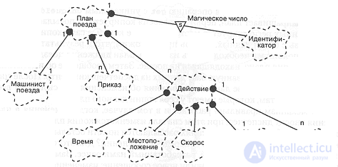
Figure 12-6. Class diagram for TrainPlan (train movement plan).
Figure 12-7 shows how copies of a plan are transmitted and updated. The primary copy of a movement plan resides in the centralized database at the dispatch center and may be distributed to any number of nodes of the network. When some client requests a plan (using the operation get with a unique UniqueId as its argument), the primary version is copied and sent to the client. The location of the copy is recorded in the database, and the copy of the plan itself retains a link to the database. Now suppose that as a result of the engineer's actions it becomes necessary to change the train movement plan. First the copy of the plan located on the train is changed. Then a message about the changes is sent to the centralized database at the dispatch center. After the plan has been changed in the database, messages about the changes are distributed to all the other clients that hold copies of that plan.
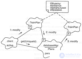
Figure 12-7. Train movement plan.
This mechanism also works correctly in the case where the dispatcher makes changes to the movement plan; in that case the copy of the plan in the database is changed first, and then messages about the changes are distributed over the network to the remaining clients. How are the changes transmitted in both cases? For this we use the message passing mechanism we developed earlier. Note that as a result of design we have added a new message: change of train movement plan. Thus the mechanism for transmitting movement plans is based on the already existing low-level message passing mechanism.
Using an off-the-shelf commercial DBMS on the dispatch computers will make it possible to provide data redundancy, recovery, audit logging, and information security.
Displaying information
Using off-the-shelf technological solutions for the database allows us to concentrate on the specifics of the problem. The same result can be achieved in the information display mechanisms if standard graphics facilities are used, for example Microsoft Windows or X Windows. Using off-the-shelf graphics software raises the level of abstraction of our system so much that developers need not worry about displaying information at the pixel level. In addition, it is very important to encapsulate design decisions about the graphical representation of various objects.
Consider, for example, displaying information about the profile and quality of sections of track. It is required that the image appear in two places: at the dispatch center and on the train (where only the track ahead of the train is displayed). Assuming that we have some class whose instances represent sections of track, we can consider two approaches to visualizing this object. Under the first approach, a special object is created to manage the display, which converts the state of the object into visual form. Under the second approach we forgo a special external object and include in each of our objects information about how to display it. We consider the second approach preferable, since it is simpler and better reflects the essence of the object model.
This approach is not without drawbacks, however. We will probably end up with a multitude of varieties of displayable objects, each of them created by different groups of developers. If each displayable object is implemented separately, then redundant code, inconsistency of style, and generally a great deal of confusion arise. It is more correct to analyze all the varieties of displayable objects, determine what elements they have in common, and create a set of intermediate classes that will provide for the display of these common elements. The intermediate classes, in turn, can be built on the basis of commercial low-level graphics packages.
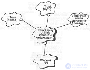
Figure 12-8. Displaying information.
Figure 12-8 shows the design decision to implement all displayable objects with the help of common class utilities. These utilities are built on the basis of a low-level Windows interface that is hidden from all the high-level classes. In reality, the Windows API procedures are hard to embody in a single class or utility. Our diagram is slightly simplified; the implementation will probably require the services of several Windows API classes and display utilities for the computer display on the train.
The principal merit of the proposed approach lies in the fact that it reduces the impact of changes that arise when the roles of hardware and software are redistributed. For example, if we have to replace our displays with more (or less) powerful ones, we will have to adjust procedures only in the class TrainDisplayUtilities. Without such a decomposition we would have to make changes in every displayable object whenever anything changed at the lower level.
The sensor polling mechanism
We said above that the traffic management system must include a large number of diverse sensors. For example, on each train sensors monitor oil temperature, fuel quantity, throttle setting, water temperature, engine load, and so on. Active sensors on wayside devices report the current position of their switches and transmit signals. All the values returned by sensors are different, but their processing can be carried out in a similar way. Suppose that our computer uses memory-mapped I/O at fixed addresses. Then the data of each sensor is read from a particular area of memory and only then interpreted in a way that depends on the specific sensor. Most sensors must be polled periodically. If the value lies within the specified limits, it is reported to some client, and nothing else happens. If, however, a sensor reading goes outside the established limits, other clients may be notified of this. Finally, if a reading goes far outside the permissible bounds (for example, the oil pressure on a locomotive rises to a dangerous level), some kind of audible alarm signal may be needed, along with notification of special clients so that decisive measures can be taken.
Reproducing this behavior for each sensor is not only tedious and error-prone, it also bloats the volume of code. If we do not identify the characteristics common to all sensors from the very beginning, various developers will propose their own solutions to one and the same problem. This, in turn, will lead to difficulties in maintaining the system. Therefore, in order to identify the common properties it is necessary to carry out an analysis of all periodically polled analog sensors and to propose a common polling mechanism for them that is acceptable for all.
We already solved an analogous problem in Chapter 8, in application to the weather monitoring station. There we created a hierarchy of sensor classes and described the mechanism for polling them. There is every reason to make use of the solution obtained earlier in our present problem as well.
This is a good example of the reuse of design decisions across different application domains.

Comments