
Lecture
Essentials: objects and their interactions
An interaction diagram is used to trace the execution of a scenario in the same context as an object diagram [These diagrams generalize Rumbaugh's event trace diagrams and Jacobson's interaction diagrams [15]]. To a certain extent an interaction diagram is simply another way of presenting an object diagram. For example, in Fig. 5-30 we see an interaction diagram that duplicates most of the semantics of the object diagram shown in Fig. 5-25. The advantage of the interaction diagram is that the order in which messages are sent is easier to read on it, while the advantage of the object diagram is that it is better suited to many objects with complex invocations and allows other information to be included: links, attribute values, roles, flowcharts and visibility. Since both types of diagram have undeniable merits, we use both in our method [Object diagrams and interaction diagrams are so close in semantics that tools can generate one diagram from the other with minimal loss of information].
Interaction diagrams do not introduce any new concepts or notation. Rather, they take the essential elements of the object diagram and rearrange them. As Fig. 5-30 shows, an interaction diagram outwardly resembles a table. The names of the objects on the interaction diagram (the same as on the object diagram) are written horizontally in its top row. Beneath each of them a vertical dashed line is drawn. The sending of messages (which may denote events or invocations of operations) is shown by horizontal arrows, with the same syntax and synchronization notation as on the object diagram. The line denoting the sending of a message is drawn from the client's vertical to the server's vertical. The first message is shown at the very top level, the second below it, and so on, so that their sequence numbers become unnecessary.
Interaction diagrams often convey the semantics of scenarios better than object diagrams in the early stages of the development life cycle, when the protocols of individual classes have not yet been identified. As we will describe in the next chapter, at the beginning of development interaction diagrams are usually focused on events rather than on operations, because events help to determine the boundaries of the system. Once the class structures have been refined, the emphasis shifts to object diagrams, whose semantics is more expressive.
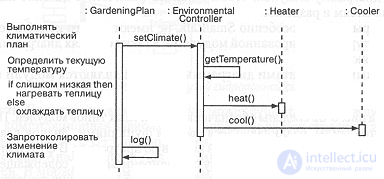
Fig. 5-31. Notes and the flow of control.
Advanced concepts
Interaction diagrams are conceptually very simple, but there are two explanatory elements that make it possible to make them more expressive in the presence of complex interaction patterns.
Notes. For complex scenarios that use conditions or iteration, an object diagram may be supplemented with notes. As shown in the example (Fig. 5-31), notes may be attached to any message to the left of the diagram at the appropriate level, in plain text, with structuring elements, or using the syntax of the implementation language.
Flow of control. Neither the simplest object diagrams nor interaction diagrams show the transfer of control. For example, if we have shown that an object A sends messages X and Y to other objects, then it remains unclear whether the messages X and Y are independent messages from A or whether they were invoked as parts of some enclosing message Z. As shown in Fig. 5-31, we can draw bars on the vertical line of each object, showing the periods when control resides in that object. In this example we see that everything is directed by an anonymous instance of the class GardeningPlan, which, while executing a climate plan, invokes other methods, which, in their turn, invoke further methods, and, in the end, control returns back to it.

Comments