
Lecture 54 min.
A class diagram shows classes and their relationships, thereby representing the logical aspect of the design. An individual class diagram represents a particular view of the class structure. In the analysis stage we use class diagrams to identify the common roles and responsibilities of the entities that provide the required behavior of the system. In the design stage we use the class diagram to convey the structure of the classes that form the architecture of the system.
The two principal elements of a class diagram are classes and their basic relationships.
Classes. Figure 5-2 shows the notation for representing a class on a diagram. A class is usually represented by an amorphous object resembling a cloud [Choosing graphical symbols is a difficult task. One must carefully balance expressiveness against simplicity, so designing icons is to a large degree an art rather than a science. We took the cloud from the materials of the Intel Corporation, which documented its original object-oriented iAPX432 architecture. The shape of this image hints at the fuzziness of the boundaries of an abstraction, from which no smoothness or simplicity is to be expected. The dashed outline symbolizes the fact that clients usually operate with instances of the class rather than with the class itself. This shape can be replaced by a rectangle, as Rumbaugh did:

However, although a rectangle is simpler to draw, this symbol is used far too often in different situations and consequently evokes no associations. Moreover, Rumbaugh's convention of denoting classes by ordinary rectangles and objects by rectangles with rounded corners conflicts with other elements of his notation (rectangles for actors in data flow diagrams and rounded rectangles for states in transition diagrams). The cloud is also more convenient for placing the adornments that, as we shall see later, are required for abstract and parameterized classes, and for that reason it is preferable in class and object diagrams. The argument that rectangles are simpler to draw is debatable when automated support for the notation is used. But in order to preserve the possibility of simple drawing and to emphasize the connection with Rumbaugh's method, we retain his notations for classes and objects as an acceptable alternative].
Every class must have a name; if the name is too long, it can be abbreviated or the icon on the diagram can be enlarged. The name of each class must be unique within the class category that contains it. For some languages, in particular C++ and Smalltalk, we must require that each class have a name that is unique within the system.
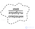
Figure 5-2. The class icon.
On some class icons it is useful to list a few of the class's attributes and operations. "On some," because for most trivial classes this is troublesome and unnecessary. The attributes and operations on the diagram represent a prototype of the complete class specification, in which all of its members are declared. If we want to see more of the class's attributes on the diagram, we can enlarge the icon; if we do not want to see them at all, we remove the dividing line and write only the class name.
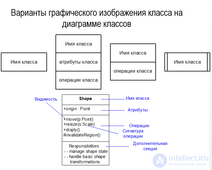
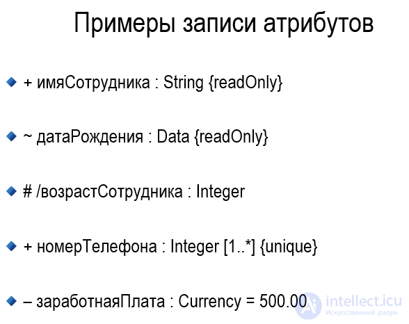
As we described in Chapter 3, an attribute denotes a part of a composite object, or aggregate. Attributes are used in analysis and design to express individual properties of a class [More precisely, an attribute is equivalent to an aggregation relationship with physical containment whose label coincides with the name of the attribute and whose cardinality is exactly one]. We use the following language-independent syntax, in which an attribute may be denoted by a name or by a class, or by both, and may possibly have a default value:
The attribute name must be unambiguous in the context of the class. Chapter 3 stated that an operation is a service provided by a class. Operations are usually shown inside the class icon by name only. To distinguish them from attributes, parentheses are added to their names. Sometimes it is useful to give the full signature of an operation:
Operation names must be understood unambiguously in the context of the class, in accordance with the operation overloading rules of the chosen implementation language.
A general principle of the notation: the syntax of elements such as attributes and operations may be adapted to the syntax of the chosen programming language. For example, in C++ we can declare some attributes as static, or some operations as virtual or pure virtual [In C++, members common to all objects of a class are declared static; a polymorphic operation is called virtual; an operation whose implementation is the responsibility of a subclass is called pure virtual]; in CLOS we can mark an operation as a method :around. In any case we make use of the specifics of the syntax of the given language to indicate details. As described in Chapter 3, an abstract class is a class that cannot have instances. Since abstract classes are very important for designing a good class structure, we introduce a special triangular icon for them with the letter A in the middle, placed inside the class icon (Figure 5-3). A general principle: adornments represent secondary information about some entity in the system. All such kinds of adornment have the same form of a nested triangle.
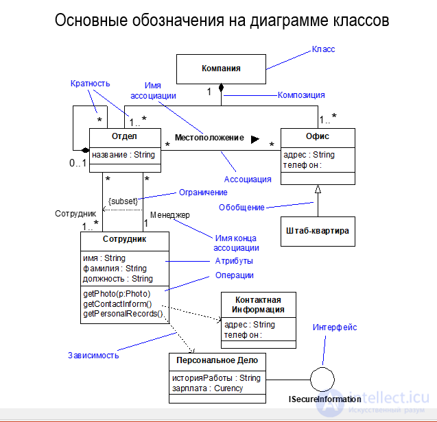
Classes are rarely isolated; on the contrary, as was explained in Chapter 3, they enter into relationships with one another. The kinds of relationship are shown in Figure 5-4: association, inheritance, aggregation (has), and using. When drawing a particular relationship, one can attach to it a textual label documenting the name of the relationship or suggesting its role. The name of a relationship need not be global, but it must be unique in its context.
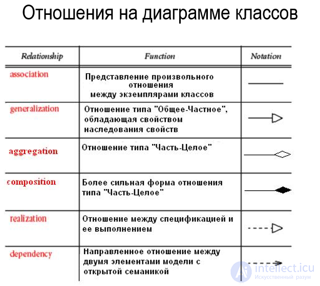
The association icon connects two classes and denotes the existence of a semantic connection between them. Associations are often labeled with nouns, for example Employment (place of employment), describing the nature of the connection. A class may have an association with itself (a so-called reflexive association). A single pair of classes may have more than one association. Next to the association icon you can indicate its cardinality (see Chapter 3), using the syntax of the following examples:
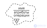
Figure 5-3. The abstract class icon.
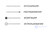
Figure 5-4. Icons for relationships among classes.
The cardinality notation is written at the end of the association line and denotes the number of links between each instance of the class at the beginning of the line and instances of the class at its end. If the cardinality is not explicitly indicated, it is assumed to be undefined.
The notations for the remaining three kinds of relationship refine the association symbol with additional adornments. This is convenient, since in the course of developing a design relationships tend to become more refined. First we assert a semantic connection between two classes, and then, after tactical decisions have been made about their true relationship, we refine this connection as inheritance, aggregation, or using.
The inheritance icon, representing the "general/specific" relationship, looks like the association icon with an arrow pointing from the subclass to the superclass. In accordance with the rules of the chosen implementation language, a subclass inherits the structure and behavior of its superclass. A class may have one (single inheritance) or several (multiple inheritance) superclasses. Name conflicts among superclasses are resolved in accordance with the rules of the chosen language. As a rule, cycles in inheritance are forbidden. A cardinality symbol is not attached to inheritance.
The aggregation icon denotes the "whole/part" relationship (the "has" relationship) and is obtained from the association icon by adding a filled circle at the end that denotes the aggregate. Instances of the class at the other end of the arrow will in some sense be parts of instances of the aggregate class. Reflexive and cyclic aggregation are permitted. Aggregation does not require the physical containment of the part within the whole.
The using symbol denotes the "client/server" relationship and is drawn as an association with an empty circle at the end corresponding to the client. This relationship means that the client needs the services of the server, that is, the operations of the client class invoke the operations of the server class or have a signature in which the return value or the arguments belong to the server class.
Example. The icons described above represent the most important elements of all class diagrams. Taken together they give the developer a set of notations sufficient to describe the foundation of the system's class structure.
Figure 5-5 shows how the task of servicing a hydroponics greenhouse system is described in this notation. This diagram represents only a small part of the system's class structure. Here we see the class GardeningPlan (gardening plan), which has an attribute called crop (crop), one modifier operation execute and one selector operation canHarvest (can harvest?). There is an association between this class and the class EnvironmentalController (environmental controller): instances of the plan specify the climate that instances of the controller must maintain.
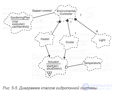
Figure 5-5. Class diagram of the hydroponics system.
This diagram also shows that the class EnvironmentalController is an aggregate: its instances contain exactly one instance each of the classes Heater and Cooler (cooling unit), and any number of instances of the class Light (lamp). Both of the classes Heater and Cooler are subclasses of the abstract class that starts a process, Actuator, which provides the protocols startUp and shutDown (start and stop, respectively), and which uses the class Temperature.
As was explained in Chapter 3, the class is a necessary but insufficient means of decomposition. When a system grows to a dozen classes, one can notice groups of classes that are internally connected and loosely coupled with the others. We call such groups class categories.
Many object-oriented languages do not support this notion. Consequently, providing a notation for class categories makes it possible to express important architectural elements that could not be written down directly in the implementation language [The Smalltalk programming environment supports the concept of class categories. This in fact is what prompted us to include categories in the notation. However, in Smalltalk class categories have no semantic content: they exist only to organize the class library more conveniently. In C++, class categories are related to the concept of components (Stroustrup); they are not yet a feature of the language, although the inclusion of namespace semantics in it is under consideration. (Namespaces have since been included in the standard. - Ed.)].

Figure 5-6. The class category icon.
Classes and class categories may coexist on the same diagram. The upper levels of the logical architecture of large systems are usually described by several diagrams containing only class categories.
Class categories serve to partition the logical model of a system. A class category is an aggregate consisting of classes and other class categories, in the same sense in which a class is an aggregate consisting of operations and other classes. Every class in the system must "live" in exactly one category or be located at the very top level of the system. Unlike a class, a class category does not have operations or states in explicit form; they are contained in it implicitly in the descriptions of the aggregated classes.
Figure 5-6 shows the icon denoting a class category. As with a class, a category requires a name, which must be unique within the given model and distinct from the names of classes.
Sometimes it is useful to list some of the classes it contains on the category icon. "Some," because categories often contain quite a few classes, and listing them all would be troublesome, and indeed unnecessary. Just like the list of attributes and operations on a class icon, the list of classes in a category icon represents an abbreviated view of its specification. If we want to see more classes on the category icon, we can enlarge it. We can remove the dividing line and leave only the category name in the icon.
A class category constitutes an encapsulated namespace. By analogy with the qualification of names in C++, the category name can be used to qualify unambiguously the names of the classes and categories it contains. For example, given a class A from category B, its full name will be A::B. Thus, as will be discussed below, for nested categories name qualification extends to an arbitrary depth.
Some classes in a category may be public, that is, exported for use outside the category. The remaining classes may be part of the implementation, that is, not used by any classes external to this category. For the analysis and design of the architecture this distinction is very important, since it makes it possible to divide responsibilities between the exported classes, which take on communication with clients, and the internal classes of the category, which actually do the work. In fact, during analysis the private aspects of a class category may be omitted. By default all classes in a category are defined as public unless the contrary is explicitly indicated. Access restriction will be discussed below.
A category may use non-nested categories and classes. Conversely, classes may also use categories. For uniformity we denote these export-import relationships in the same way as the using relationship between classes (see Figure 5-4). For example, if category A uses category B, this means that classes from A may be descendants of, or contain instances of, use, or be in some other way associated with classes from B.
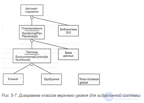
Figure 5-7. Top-level class diagram for the hydroponics system.
When a category contains too many common classes, such as base container classes or other base classes similar to Object in Smalltalk, practical difficulties arise. Such classes will be used by nearly all the other categories, cluttering up the root level of the diagram. To get around this, such categories are marked with the keyword global in the lower left corner of the icon, showing that by default the category may be used by all the others.
Top-level class diagrams containing only class categories represent the architecture of the system in its most general form. Such diagrams are extremely useful for visualizing the layers and partitions of a system. A layer denotes a set of class categories at the same level of abstraction. Thus, layers represent a set of class categories, just as class categories are clusters of classes. Layers are usually needed in order to isolate the upper levels of abstraction from the lower ones. Partitions denote class categories that are related (in some way) at different levels of abstraction. In this sense layers are horizontal slices of the system, and partitions are vertical ones.
Example. Figure 5-7 gives an example of a top-level class diagram for the greenhouse operation. This is a typical layered system. Here the abstractions that are closer to reality (namely, the actuators and the climate and nutrient sensors) are located at the very lowest levels, while the abstractions reflecting the user's concepts are closer to the top. The class category CropTypes is global, that is, its services are available to all the other categories. On the icon of the class category Planning two of its important classes are shown: GardeningPlan from Figure 5-5 and PlanAnalyst (plan analyst). If any of the eight class categories shown in the figure is enlarged, the classes composing them will be revealed.
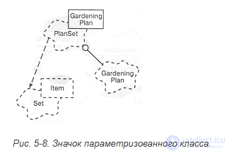
Figure 5-8. The parameterized class icon.
Up to now we have been dealing with the essential part of our notation [All the essential elements taken together are precisely what forms the Booch Lite notation]. However, in order to convey certain frequently encountered strategic and tactical decisions, we shall have to extend it. The general rule: stick to the essential concepts and notations, and use the additional ones only when they are truly necessary.
Parameterized classes. In some object-oriented programming languages, in particular C++, Eiffel, and Ada, it is possible to create parameterized classes. As was said in Chapter 3, a parameterized class is a family of classes with a common structure and behavior. To create a concrete class of this family, actual parameters must be substituted for the formal ones (the process of instantiation). A concrete class can give rise to instances.
Parameterized classes differ quite strongly from ordinary ones, which is indicated by a special adornment on their icons. As the example in Figure 5-8 shows, a parameterized class is drawn as an ordinary class icon with a dashed rectangle in the upper right corner in which the parameters are indicated. An instantiated class is drawn as an ordinary class icon with an adornment in the form of a rectangle (with a solid border) listing the actual parameters.
The relationship between a parameterized class and its instantiation is drawn as a dashed line pointing to the parameterized class. To obtain an instantiated class, another concrete class is required as an actual parameter (GardeningPlan in this example).
A parameterized class cannot give rise to instances and cannot itself be used as a parameter. Each instantiated class is a new class, distinct from the other concrete classes of the same family.
Metaclasses. In some languages, such as Smalltalk and CLOS, there are metaclasses. A metaclass (see Chapter 3) is the class of a class. In Smalltalk, for example, metaclasses are the mechanism supporting class variables and operations (similar to static class members in C++), and especially class factories (producing operations) that create instances of objects of the given class. In CLOS, metaclasses play an important role in the ability to refine the semantics of the language.
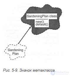
Figure 5-9. The metaclass icon.
Metaclasses differ fundamentally from ordinary classes, and to emphasize this their icon is shaded gray, as is done in Figure 5-9. The relationship between a class and its metaclass (the metarelationship) takes the form of a bold arrow directed from the class to its metaclass. The metaclass GardeningPlan provides the factory methods new() and default(), which create new instances of the class GardeningPlan.
A metaclass has no instances, but it may be associated in any manner with other classes.
The metarelationship has one more use. On some class diagrams it is useful to indicate an object that is a static member of some class. To show the class of this object, we can draw an "object/class" metarelationship. This is consistent with the previous usage: a relationship between some entity (an object or a class) and its class.
Class utilities. Owing to their origins, hybrid languages such as C++, Object Pascal, and CLOS allow the developer to use both a procedural and an object-oriented style of programming. This contrasts with Smalltalk, which is organized entirely around classes. In a hybrid language there is the possibility of describing a non-member function, also called a free subprogram. Free subprograms often arise during analysis and design at the boundary of the object-oriented system and its procedural interface with the outside world.
Class utilities are used in one of two ways. First, a class utility may contain one or more free subprograms, in which case one simply lists logical groups of such non-member functions. Second, a class utility may denote a class having only class variables (and operations) (in C++ this would mean a class with only static members [Smalltalk programmers often use the utility idiom to achieve the same effect]). There is no point in such classes having instances, because all the instances would be in one and the same state. Such a class itself acts as its own sole instance.
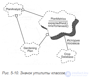
Figure 5-10. The class utility icon.
As shown in Figure 5-10, a class utility is denoted by an ordinary class icon with an adornment in the form of a shadow. In this example the class utility PlanMetrics provides two important operations: expectedYield and timeToHarvest (time to harvest). The utility provides these two operations on the basis of the services offered by the lower-level classes GardeningPlan and CropDatabase (crop database). As the diagram shows, PlanMetrics depends on CropDatabase: it obtains information about crop history from it. In turn, the class PlanAnalyst uses the services of PlanHetrics.
Figure 5-10 illustrates the usual use of class utilities: here the utility provides services based on two independent lower-level abstractions. Instead of associating these operations with higher-level classes such as PlanAnalyst, we decided to collect them into a class utility and achieved a clear division of responsibilities between these simple procedural facilities and the more sophisticated abstraction of the analyzer class PlanAnalyst. In addition, including free subprograms in a single logical structure increases the chances of their reuse, providing a more precise partitioning of the abstraction.
The relationship of classes with a utility may be a using relationship, but not inheritance or aggregation. In turn, a class utility may enter into a using relationship with other classes and contain static instances of them, but it cannot inherit from them.
Like classes, utilities may be parameterized and instantiated. To denote parameterized utilities, the same adornments are used as for parameterized classes (see Figure 5-8). Similarly, to denote the relationship between a parameterized class utility and its instantiation we use the same notation as for the instantiation of parameterized classes.
Nesting. Classes may be physically nested within other classes, and class categories within other categories, and so on. Usually this is needed in order to restrict the visibility of names. Nesting corresponds to declaring the nested entity within its enclosing context. We depict nesting by a physically nested icon; in Figure 5-11 the full name of the nested class is Nutritionist::NutrientProfile.
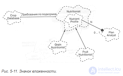
Figure 5-11. The nesting icon.
In accordance with the rules of the chosen implementation language, classes may contain instances of a nested class or use it. Languages usually do not permit inheritance from a nested class.
Usually the nesting of classes is a tactical decision of the designer, while the nesting of class categories is a typically strategic architectural decision. In both cases the need to use nesting to a depth of more than one or two levels is encountered extremely rarely.
Export control. All the major object-oriented programming languages make it possible to separate clearly the interface of a class and its implementation. In addition, as described in Chapter 3, most of them allow the developer to define access to the class interface in more detail.
For example, in C++ the members of a class may be public (accessible to all clients), protected (accessible only to subclasses, friends, and the class itself), and private (accessible only to the class itself and its friends). Moreover, some members may be part of the implementation of the class and thereby be inaccessible even to friends of this class [For example, an object or class described in a .cpp file is accessible only to member functions implemented in the same file]. In Ada, class members may be public or private. In Smalltalk all instance variables are private by default and all operations are public. Access is granted by the class itself and only explicitly: a client cannot obtain anything by force.
We depict the mode of access with the following relationship adornments:
We place them as "tick marks" on the relationship line at the source. For example, Figure 5-12 shows that the class GrainCrop inherits multiply from the classes Crop (a public superclass) and FoodItem (a protected superclass).
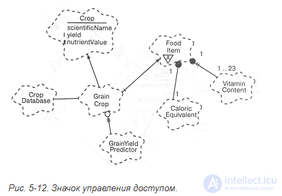
Figure 5-12. The access control icon.
FoodItem in turn contains from one to twenty-three private instances of the class VitaminContent and one public instance of the class CaloricEquivalent (caloric value). Note that CaloricEquivalent could have been written as an attribute of the class FoodItem, since attributes are equivalent to aggregation whose cardinality equals 1:1. In addition, we see that the class GrainCrop uses the class GrainYieldPredictor as part of its implementation. This usually means that some method of the class GrainCrop uses services provided by the class GrainYieldPredictor.
Besides the cases already considered in this example, an ordinary association may likewise be adorned with access symbols. A metarelationship (the relationship between an instantiated class and its metaclass) cannot receive such adornments.
Access restriction symbols may be applied to nesting in all its forms. On the class notation we can indicate access to attributes, operations, or nested classes by adding an access restriction symbol as a prefix to the name. For example, Figure 5-12 shows that the class Crop has one public attribute scientificName (scientific name), one protected one, yield (yield), and one private one, nutrientValue (nutrient quantity). The same notations are used for nested classes or class categories. By default all nested classes and categories are public, but we can indicate restricted access with the appropriate mark.
Kinds of relationships. In some languages there are kinds of relationships so pervasive, with semantics so fundamental, that introducing new symbols would be justified. In C++, for example, there are three such constructs:
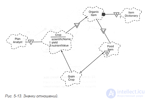
Figure 5-13. Relationship icons.
It is logical to use for them the same adornment in the form of a triangular icon as for an abstract class, but with the symbols S, V or F respectively.
Consider the example in Figure 5-13, which presents another view of the classes shown in the previous figure. We see that the base class OrganicItem contains one instance of the class ItemDictionary and that this instance is contained by the class itself rather than by its instances (that is, it is shared by all instances). In the general case we place the static notation at one of the ends of an association or at the end of an aggregation relationship.
Considering the class GrainCrop, we see that the inheritance structure takes on a diamond shape (the inheritance relationships branch out and then converge). By default, in C++ a diamond-shaped inheritance structure leads to the structures of the base class inherited twice being duplicated in the leaf classes. In order for the class GrainCrop to receive a single copy of the twice-inherited structures of the class OrganicItem, we must apply virtual inheritance, as shown in the figure. We can add the virtual relationship adornment only to inheritance.
The friendship icon may be attached to any kind of relationship, placing the icon closer to the server, implying that the server considers the client its friend. For example, in Figure 5-13 the class PlanAnalyst is a friend of the class Crop, and consequently has access to its private and protected members, including both of the attributes yield and scientificName.
Physical containment. As was shown in Chapter 3, the aggregation relationship is a special case of association. Aggregation denotes a "whole/part" hierarchy and implies that from the aggregate one can find its parts. A "whole/part" hierarchy does not imply mandatory physical containment: a trade union has members, but this does not mean that it owns them. On the other hand, an individual record about a crop does physically contain within itself the corresponding information, such as the name of the crop, the yield, and the nutrient schedule.
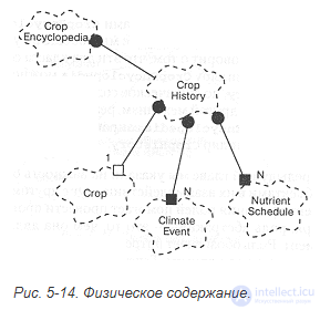
Figure 5-14. Physical containment.
Aggregation is usually discovered during analysis and design; refining it as physical containment is a detailed, tactical decision. However, recognizing this case is important, first, for correctly defining the constructors and destructors of the classes involved in the aggregation, and second, for generating and consistently revising code.
Physical containment is marked on the diagram by an adornment at the end of the line denoting aggregation; the absence of this adornment means that the decision about physical containment has not been made. In hybrid languages we distinguish two kinds of containment:
In purely object-oriented languages, especially in Smalltalk, physical containment is only by reference.
To distinguish the physical presence of an object from a reference to it, we use a filled square to denote aggregation by value and an empty square for aggregation by reference. As will be discussed later, this style of adornment is consistent with the corresponding semantics on object diagrams.
Consider the example given in Figure 5-14. We see that instances of the class CropHistory physically contain several instances of the classes NutrientSchedule and ClimateEvent (climatic event). Physical containment of the parts of an aggregation by value means that their creation or destruction takes place when the aggregate itself is created or destroyed. Thus, aggregation by value guarantees that the lifetime of the aggregate coincides with the lifetime of its parts. In contrast to this, each instance of the class CropHistory possesses only a reference or pointer to one instance of the class Crop. This means that the lifetimes of these two objects are independent, although here too one is a physical part of the other. Yet another case is the aggregation relationship between the classes CropEncyclopedia and CropHistory. In this case we do not mention physical containment at all. The diagram says that these two classes stand in a "whole/part" relationship, and that from an instance of CropEncyclopedia one can find the corresponding instance of CropHistory, but physical containment has nothing to do with it. Instead, some other mechanism implementing this association may be devised. For example, an object of the class CropEncyclopedia queries a database and obtains a reference to the appropriate instance of CropHistory.
In the previous chapter we pointed out the importance of describing the various roles played by objects in their interaction with one another; in the next chapter we shall study how the identification of roles helps to carry out the process of analysis.
In short, the role of an abstraction is what it is to the outside world at a given moment. A role denotes the need or the capability by virtue of which one class is associated with another. A textual adornment describing the role of a class is placed next to any association, closer to the class fulfilling the role, as can be seen in Figure 5-15. In this figure the classes PlanAnalyst and Nutritionist are both suppliers of information for an object of the class CropEncyclopedia (they both add information to the encyclopedia), while objects of the class PlanAnalyst are also users (they browse material from the encyclopedia). In any case, the role of the client determines its individual behavior and the protocol it uses. Let us also note the reflexive association of the class PlanAnalyst: we see that several instances of this class may collaborate with one another, and in doing so they use a special protocol that differs from their behavior in an association with, for example, the class CropEncyclopedia.
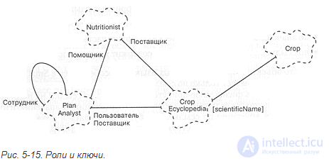
Figure 5-15. Roles and keys.
This example also shows an association between the classes CropEncyclopedia and Crop, but with a different kind of adornment, which represents a key (drawn as an identifier in square brackets). A key is an attribute whose value uniquely identifies an object. In this example the class CropEncyclopedia uses the attribute scientificName, as the key for finding the required record. Generally speaking, a key must be an attribute of the object that is a part of the aggregate, and it is placed at the far end of the association relationship. It is possible to use several keys, but the key values must be unique.
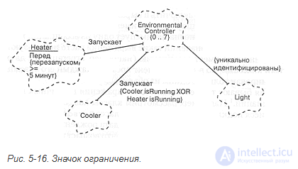
Figure 5-16. The constraint icon.
Constraints. As was said in Chapter 3, a constraint is the expression of some semantic condition that must be preserved. In other words, a constraint is an invariant of a class or a relationship that must hold if the system is in a stable state. Let us emphasize: in a stable state, because transient phenomena are possible in which the state of the system as a whole is changing and the system is in an internally inconsistent state, so that it is impossible to observe all the imposed constraints. Constraints are guaranteed to be observed only in a stable state of the system.
For constraints we use adornments similar to those we used to denote roles and keys: we place the constraint expression, enclosed in curly braces, next to the class or relationship to which it applies. A constraint is attached to individual classes, to an association as a whole, or to its participants.
In Figure 5-16 we see that for the class EnviromentalController a constraint has been imposed on cardinality, postulating that there are no more than 7 instances of this class in the system. In the absence of a constraint on cardinality, a class may have any number of instances. The notation for an abstract class introduced earlier is a special case of a constraint (zero instances), but since this phenomenon occurs very frequently in class hierarchies, it has been given its own kind of adornment (a triangle with the letter A).
The class Heater has a constraint of a different kind. The figure includes the requirement of hysteresis in the operation of the heater: it cannot be turned on if less than five minutes have passed since it was last turned off. We attach this constraint to the class Heater, considering that responsibility for observing it rests with the instances of the class.
This diagram shows two more kinds of constraint: constraints on associations. In the association between the classes EnvironmentalController and Light it is required that the individual light sources be uniquely indexed relative to one another in the context of this association. There is also a constraint imposed on the associations of EnvironmentalController with the classes Heater and Cooler, consisting in the fact that the controller cannot turn on the heater and the cooler at the same time. This constraint is applied to the association and not to the classes Heater and Cooler, because observing it cannot be entrusted to the heaters and coolers themselves.
If necessary, the names of other associations can be included in a constraint expression by means of the qualified names used in the design. For example, Cooler:: starts unambiguously names one of the associations of the controller class. In our notation such expressions are often used in the situation where one class has an association (for example, an aggregation) with two (or more) other classes, but at any moment in time each of its instances may be associated with only one of the objects.
Constraints are also useful for expressing derived classes, attributes, and associations [In Rumbaugh's terminology these are called derived entities: he uses a special icon for them. Our general approach to constraints is sufficient to express the semantics of derived classes, attributes, and associations; this approach makes it easier to reuse existing icons and to define unambiguously the entities from which the derivations are taken]. For example, consider the classes Adult and Child (children), which are subclasses of the abstract class Person (People). We can supply the class Person with an attribute dateofbirth and add an attribute called age (age), for example because age plays a special part in our model of the real world. However, age is a derived attribute: it can be determined from dateofbirth. Thus, in our model we can have both attributes, but we must indicate a constraint defining the derivation of one from the other. The question of which attributes are derived from which belongs to tactics, but the constraint will be useful regardless of the decision we adopt.
Similarly, we could have an association between the classes Adult and Child, which would be called Parent (parent), and we could also include an association named Caretaker if this is needed in the model (for example, if formal parenting relationships are being modeled in a social welfare system). The Caretaker association is derived: it can be obtained as a consequence of the Parent; we can indicate this invariant as a constraint imposed on the association Caretaker.
The last additional concept is connected with the task of modeling the properties of associations; in the notation the task is solved by introducing an element that may be attached to any diagram.
Consider the example in Figure 5-17. It shows a many-to-many association between the classes Crop and Nutrient. This association means that N (any number) of nutrients are applied to each crop, and each nutrient is applied to N (any number) of crops. The class NutrientSchedule is, as it were, a property of this many-to-many relationship: each of its instances corresponds to a pair consisting of a crop and a nutrient. To express this semantic fact, we draw on the diagram a dashed line from the association Crop/Nutrient (the association with an attribute) to its property, the class NutrientSchedule (the attribute of the association). Each unique association may have no more than one such attribute, and its name must correspond to the name of the attribute class.
The idea of attributing associations admits of a generalization: during analysis and design a multitude of temporary assumptions and decisions arise; their sense and purpose are often lost, because there is no suitable place to store them, and to keep everything in one's head is unthinkable. It is therefore useful to introduce a notation that allows arbitrary textual notes to be added to any element of a diagram. In Figure 5-17 there are two such notes. One of them, attached to the class NutrientSchedule, says something about the expected uniqueness of its instances (Selects from the general set of schedules); the other (Obtained from the nutrient database) is attached to a particular operation of the class Nutrient and expresses our wishes regarding its implementation.
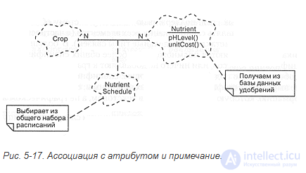
Figure 5-17. An association with an attribute, and a note.
For such notes we use icons resembling slips of paper, and we connect them to the element they refer to with a dashed line. Notes may contain any information: ordinary text, program fragments, or references to other documentation (all of this may prove useful in developing design tools). Notes need not be connected with any element, which means that they refer to the diagram itself [The icon we use resembles the notation for notes in many windows systems, especially those following the Macintosh traditions. The immediate inspiration for our notation was the proposals of Gamma, Helm, Johnson, and Vlissides .
A specification is a non-graphical form used to describe completely an element of the notation: a class, an association, an individual operation, or an entire diagram. By looking through diagrams one can get one's bearings in a large system relatively easily; however, a graphical representation alone is not enough: we must have certain explanations to accompany the pictures, and specifications will play this part.
As was said earlier, a diagram is a slice of the system model being developed. Specifications, on the other hand, serve as non-graphical justifications for each element of the notation. Thus, the set of all syntactic and semantic facts that have found reflection on a diagram must be a subset of the facts described in the specification of the model, and must be consistent with them. Obviously, a design tool supporting such a notation can play an important part in maintaining consistency between diagrams and specifications.
In this section we shall first consider the basic elements of the two most important specifications, and then study their additional properties. We do not set ourselves the task of describing every specification in detail — that depends on the user interface of the particular environments supporting our notation. Nor shall we present the specifications of all the elements (in particular, the metaclass and individual kinds of relationships will fall outside our attention). For the most part such specifications either are a subset of more general specifications, such as class specifications, or add nothing to the graphical representation. It is especially important to emphasize the following: a specification must reflect what is not expressed in the graphical elements of a diagram; specifications contain the information that is better written down in textual rather than graphical form.
Common elements. All specifications have at least the following components:
Name: identifier
Definition: text
The uniqueness of a name depends on the element being named. For example, class names must be unique at least within the category containing them, whereas operation names have a scope local to the class containing them.
The definition is text identifying the concept or function represented by the element and suitable for inclusion in the project dictionary (which is discussed in the next chapter).
Each specification contains a minimum of information. Of course, the automated design tool being used may introduce its own fields for the needs of a particular software environment. However, it is important to point out that no matter how many fields a specification includes, one should not impose on the developer stupid rules by which he is obliged to fill in all parts of the specification before proceeding to the next stage of development. A notation should make development easier, not create additional difficulties.
Class specifications. Each class in a model has exactly one specification, which contains at least the following items:
Responsibilities: text
Attributes: list of attributes
Operations: list of operations
Constraints: list of constraints
As was said in the previous chapter, the responsibilities of a class are the list of behavioral guarantees it provides. In the next chapter it will be shown how we use this field to record the responsibilities of classes that we discover or invent in the course of development.
The remaining items — attributes, operations, constraints — correspond to their graphical counterparts. Some operations may be so important that they should be provided with their own specifications, which we shall discuss below.
The basic concepts listed can be represented in terms of the chosen implementation language. In particular, all this information is, as a rule, unambiguously captured by a class declaration in C++ or a package specification in Ada.
As was said in Chapter 3, the behavior of certain important classes is often best expressed in the language of finite state machines, so we shall include an additional field in the class specification:
State machine: reference to a state machine
The use of the additional elements of the notation requires the following items to be introduced into the class specification:
Export control: public | implementation
Cardinality: expression
The sense of these items is entirely identical to that of their graphical counterparts. Parameterized and instantiated classes must include the following item:
Parameters: list of formal or actual parameters
The following optional items have no graphical counterparts; they serve to indicate certain functional aspects of a class:
Persistence: transitory | persistent
Concurrency: sequential | guarded | synchronous | active
Space complexity: expression
The first of these properties reflects the lifetime of objects of the class: a persistent entity is one whose state can outlive the object itself, in contrast to transitory ones, whose state disappears when the object's lifetime expires.
The second property shows to what degree the class can work in a multithreaded system (see Chapter 2). By default, objects are sequential, that is, designed for a single thread. Guarded and synchronous classes "withstand" several threads. A guarded class, however, expects the client threads to arrange mutual exclusion among themselves somehow, so that only one of them works with it at any given moment. A synchronous class itself provides mutual exclusion of clients. Finally, an active class has its own thread.
The last item contains information about the absolute or relative memory consumption of objects of this class. We can use this field to compute the size of the class or of its instances.
Operation specifications. For all member operations of classes and for free subprograms, our specifications include the following basic items:
Return class: reference to a class
Arguments: list of formal arguments
These fields can be filled in in the chosen implementation language. In accordance with the rules of the language, one more item can be included:
Qualification: text
In C++, for example, this item may contain a statement of whether the operation is static, virtual, pure virtual, or const.
The use of the additional elements of the notation requires an additional field to be introduced:
Access: public | protected | private | implementation
The content of this field depends on the implementation language. For example, in Object Pascal all attributes and operations are always public, in Ada operations may be public or private, and in C++ any of the four cases indicated are possible.
The use of the additional elements of the notation also requires the introduction of the field
Protocol: text
This field comes from the practice of the Smalltalk language: the protocol of an operation has no semantic significance but serves simply to name a logical grouping of operations, such as initialize-release or model access.
The following optional fields have no graphical counterparts and serve for the formal description of the semantics of an operation:
Preconditions: text | reference to program text | reference to an object diagram
Semantics: text | reference to program text | reference to an object diagram
Postconditions: text | reference to program text | reference to an object diagram
Exceptions: list of exceptions
The first three items may be filled in in any of the forms listed. The last contains a list of exceptions containing the names of the corresponding classes.
The last series of optional fields serves to describe certain functional aspects of an operation:
Concurrency: sequential | guarded | synchronous
Space complexity: expression
Time complexity: expression
The first two are analogous to the fields of the same name in a class specification. The third comprises relative or absolute estimates of the execution time of the operation.

Comments