
Lecture
Essentials: objects and their relationships
An object diagram shows the existing objects and their links in the logical design of the system. In other words, an object diagram represents a snapshot of the flow of events in some configuration of objects. Thus object diagrams are a kind of prototype: each represents the interaction or structural links that may arise among a given set of class instances, regardless of which concrete instances participate in that interaction. In this sense, an individual object diagram is a view of the system's object structure. During analysis we use object diagrams to show the semantics of the primary and secondary scenarios that trace the system's behavior. During design we use object diagrams to illustrate the semantics of the mechanisms in the logical design of the system. The essential elements of an object diagram are objects and their relationships.
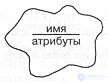
Fig. 5-23. The object icon.
Objects. Fig. 5-23 shows the icon that depicts an object on an object diagram. As in class diagrams, a horizontal line may be drawn dividing the text inside the object icon into two parts: the object's name and its attributes.
The object's name follows the syntax for attributes, and may either be written in one of the three following forms:
or use the syntax of the chosen implementation language. If the text does not fit inside the icon, one should either enlarge the icon or shorten the text. If several object icons on one diagram use one and the same unqualified name (that is, a name without an indication of the class), then they denote one and the same object. Otherwise each icon denotes a separate object [A single diagram may contain object icons with identical unqualified names but belonging to different classes, in the case where those classes have a common ancestor. This makes it possible to represent the propagation of operations from a subclass to a superclass and vice versa]. If objects with identical unqualified names appear on different diagrams, then they are different objects, unless their names are explicitly qualified.
The meaning of unqualified names depends on the context of the object diagram. More precisely: object diagrams defined at the very top level of the system have global scope; other object diagrams may be defined for class categories, individual classes or individual methods, and hence have the corresponding scopes. A qualified name may be used when it is necessary to refer explicitly to global objects, class variables (static members in C++), method parameters, attributes, or locally defined objects within the same scope.
If the class of an object is not indicated - neither explicitly, using the syntax mentioned earlier, nor indirectly, through the object's specification - then the class is regarded as anonymous, and in that case no semantic checking can be performed either of the operations carried out on the object or of its links with other objects on the diagram. If, on the other hand, only the class is indicated, then the object is considered anonymous. Every icon without an object name denotes a separate anonymous object.
In any case, the name of the object's class must be the name of a real class (or of any of its superclasses) within the scope of the diagram, used to instantiate the object, even if that class is abstract. These rules make it possible to write a scenario without knowing exactly which subclasses the objects belong to.

Fig. 5-24. The icon for a link between objects.
On object icons it is sometimes useful to indicate several of their attributes. "Several" - because the object icon represents only one particular view of its structure. The syntax of attributes coincides with the syntax of class attributes described earlier and makes it possible to indicate a default expression. The names of an object's attributes must correspond to attributes defined in the object's class, or in any of its superclasses. The syntax of attribute names may be adapted to the syntax of the implementation language.
An object diagram may also include icons denoting class utilities and metaclasses: these concepts are similar to objects, since they can act as objects and can be operated upon as objects.
Relationships between objects. As was said in Chapter 3, objects interact with other objects through links, whose notation is shown in Fig. 5-24. Just as an object is an instance of a class, a link is an instance of an association.
A link between two objects (including class utilities and metaclasses) can exist if and only if an association exists between the corresponding classes. An association between classes may manifest itself in various ways, for example, as a simple association, an inheritance relationship, or an aggregation relationship. Consequently, the existence of associations between two classes means the existence of a communication path (that is, a channel of communication) between their instances, along which the objects can send messages to one another. All classes implicitly have associations with themselves and, consequently, an object can send a message to itself.
Suppose there are objects A and B and a link L between them. Then A may invoke any operation available in the class B and accessible to A. The same is true for operations on A invoked by B. The object that invokes an operation is called the client object, and the object that provides the operation is called the server object. Usually the sender of a message knows the receiver, but the converse is not necessarily true.
In a steady state the class and object structures of the system must be consistent. If we show on the diagram an operation M on the class B, invoked over the link L, then m must be declared in the specification of B, or in the specifications of its superclasses.
As shown in Fig. 5-24, a set of messages may be written next to the corresponding link on the diagram. Each message consists of the following three elements:
We show the direction of the message by an arrow pointing at the server object. This symbol denotes the simplest form of message passing, whose semantics is guaranteed only in the presence of a single thread of control. There exist more advanced forms of synchronization, which are applicable in the case of several threads. We will describe them in the next section.
The invocation of an operation is the most common form of message. It follows the previously described syntax for operations, but, unlike it, actual parameters matching the operation's signature may be given here:
Actual parameters are matched with formal ones in order of appearance. If the object returned by the operation or the actual parameters use unqualified names that coincide with other unqualified names on the diagram, then it is implied that they name the same objects, and consequently their classes must match the operation's signature. In this way we can represent interactions in the course of which objects are passed as parameters or returned as the result of an operation.
A message may notify of an event. It follows the previously defined syntax for events, and, consequently, may represent a symbolic name, an object, or the name of some operation. In any case, the name of the event must be defined on the state transition diagram corresponding to the class of the server object. If the event notification is an operation, then it may include actual parameters.
If a sequence number is not explicitly indicated, then the message may be sent independently of the other messages indicated on the given object diagram. To indicate an explicit order of events, we may number them. Numbering begins with one and is added as an optional prefix to the operation invocation or event notification. The sequence number shows the relative order in which messages are sent. Messages with identical numbers are not ordered with respect to one another; a message with a lower sequence number is sent before a message with a higher number. Repetition of sequence numbers or their absence indicates a partial ordering of messages.
Example. Fig. 5-25 shows an object diagram for our greenhouse operation in the context of the class category Planning (described in Fig. 5-7). The purpose of this diagram is to illustrate a scenario of the execution of a common system function, namely, forecasting the costs of harvesting a particular crop.
Carrying out this function requires the cooperation of several different objects. The scenario begins with the object PlanAnalyst invoking the operation timeToHarvest() on the class utility PlanMetrics. In doing so, the object c is passed as an actual parameter of the operation. Then the utility PlanMetrics invokes the operation status() on some unnamed object of the class GardeningPlan (a gardening plan). The note says: "It must be checked that this plan is actually being carried out". In its turn, the object GardeningPlan invokes the operation maturationTime() on a selected object of the class GrainCrop, requesting the expected maturation time of the crop. When this selector operation has been executed, control returns to the object of the class PlanAnalyst, which then directly invokes the operation C.yield(), inherited from the superclass (the operation Crop::yield()). Control returns once again to the object of the class PlanAnalyst, which continues the scenario by performing on itself the operation netCost().
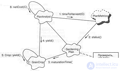
Fig. 5-25. Object diagram of the hydroponics system.
The diagram shows a link between objects of the classes PlanAnalyst and GardeningPlan. Although no messages are sent between them, the link reflects the existence of a semantic dependency between these objects.
Advanced concepts
What we have described constitutes the essential elements of an object diagram. However, many convoluted development problems require some extension of the notation used. We gave a warning when describing class diagrams and want to stress it again: advanced concepts should be used only when necessary.
Roles, keys and constraints. Above we said that on a class diagram, when an association is depicted, its role may be written next to it, denoting the intent or the cardinality of one class's link with another. For some object diagrams it is useful to write this role again when indicating a link between objects. Such a label helps to explain why one object operates on another.
Fig. 5-26 gives an example of the use of this advanced notation. Here we see that some object of the class PlanAnalyst enters information about a particular crop (Crop) into an anonymous CropEncyclopedia object, and does so while acting in the role of Author.
Using the same notation as for the class diagram, we can indicate the keys or constraints associated with an object or a link.
Data flow. As was described in Chapter 3, data may be passed either along or against the direction in which a message is sent. Sometimes an explicit indication of the direction of data transfer helps to explain the semantics of a particular scenario. We use for this an icon borrowed from the notation of structured design. Fig. 5-26 gives an example of its use: here it is shown that after the message insert completes, the value succeeded is returned. Either an object or a value may be passed and returned.
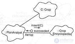
Fig. 5-26. Roles.
Visibility. In some convoluted scenarios it is useful to indicate exactly how one object sees the others. Associations on class diagrams denote a semantic dependency between classes, but do not indicate exactly how their instances see one another. For this purpose we can adorn the links on our diagrams with icons illustrating the visibility of one object to another. This information is also important for tools that generate code, or conversely, recover the logical model from the code.
Fig. 5-27 refines Fig. 5-25 and contains several adornments giving information about visibility. They resemble the adornments for physical containment on a class diagram. Inside these adornments letter designations of the type of visibility are placed.
For example, the communication channel from the object PlanAnalyst to the class utility PlanMetrics is marked with the letter G; this means that the class utility is global. The object C is seen differently by the object PlanAnalyst and by the object GardeningPlan: from the point of view of the first, the object c of the class GrainCrop is seen as a parameter of some operation (denoted by the letter P); from the point of view of the second, C is seen as an attribute or field, that is, as part of an aggregate object (denoted by the letter F (field)).
In general, the following notations may be used to indicate visibility:
In keeping with the adornment for physical containment, the adornment for visibility is an unfilled square with a letter (if the object is shared) or a filled square with a letter (if it is not shared). If the visibility adornment is not indicated, this means that the decision about the exact type of visibility has been left unspecified. In practice these adornments are attached only to a few key communication channels on an object diagram. Most often these adornments are indicated for a "part/whole" relationship (aggregation) between two objects; the second most common use for them is to represent objects that, according to the diagram's scenario, are sent as parameters.
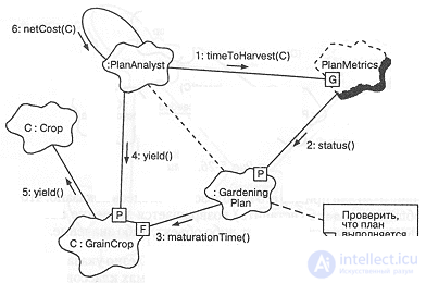
Fig. 5-27. Visibility icons.
Active objects and synchronization. As was noted in Chapter 3, some objects may be active, that is, they are allotted a separate thread of control. Other objects may exist only in a single-threaded environment. Still others, being single-tasking by nature, are guaranteed to port to a multithreaded environment.
In each of these cases we must answer two questions: how to distinguish the active objects that drive the scenario, and how to represent the various forms of object synchronization.
Earlier, when speaking about the advanced elements of class specifications, we noted that there are four kinds of semantics: sequential, guarded, synchronous and active. In essence, all objects of a class inherit the corresponding semantics of the class; all objects are considered sequential unless explicitly stated otherwise. We can explicitly show the multitasking semantics of an object on an object diagram by indicating in the lower left corner of the object icon one of the words sequential, guarded, synchronous or active. For example, in Fig. 5-28 we see that the objects H, C and a certain instance of the class EnvironmentalController are active. Unmarked objects, such as L, are considered sequential.
The message synchronization symbol introduced earlier (a simple arrow) represents ordinary sequential message passing. However, in the presence of several threads of control we must also indicate other forms of synchronization. The example in Fig. 5-28, perhaps somewhat contrived, illustrates the various types of message synchronization that may appear on an object diagram. The message turnOn() is an example of simple message passing; it is depicted by a simple arrow. The semantics of simple message passing is guaranteed only in a single-threaded environment. The remaining messages in this example use some forms of process synchronization. All such additional kinds of synchronization apply only to servers that are not sequential.
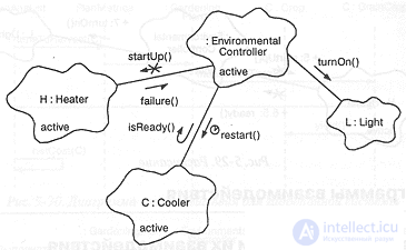
Fig. 5-28. Active objects and synchronization.
For example, the message startUp() is synchronous, that is, the client will wait until the server accepts the message. Sending a synchronous message is equivalent to the task rendezvous mechanism of the Ada language (rendezvous). In the case of the message isReady() the client will balk if the server cannot process it immediately. The message restart() will be timed out by the client if the server cannot process it within the indicated interval of time.
In each of the three latter cases the client must wait until the server processes the message, or abandon the send, after which control may be resumed. The message failure has different semantics. This is an example of an asynchronous message, which implies that the client sends an event to the server for processing, the server queues the message, and the client continues working. Such asynchronous messages are akin to interrupts.
Timing. In programs that have timing constraints, it is important to track the elapsed time from the beginning of each scenario. To denote relative time (in seconds) we place a plus sign. For example, in Fig. 5-29 the message startUp() is invoked for the first time 5 seconds after the beginning of the scenario; next, 6.5 seconds after the beginning of the scenario comes the message ready() and then, 7 seconds after the beginning of the scenario, the message turnOn().
Specifications
As with class diagrams, specifications may stand behind every element of an object diagram. The specifications of objects and their links carry no information other than what has already been described. On the other hand, the specifications of object diagrams as a whole can convey something important. As mentioned earlier, every object diagram exists in a context. In the specification the context is indicated as follows:
Context: global | category | class | operation
In particular, the scope of an object diagram may be global, or in the context of an indicated class category, class or operation (including both methods and free subprograms).
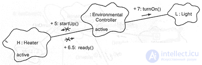
Fig. 5-29. Timing.

Comments