
Lecture
Essentials: states and transitions
A state transition diagram shows: the state space of a given class; the events that cause a transition from one state to another; and the actions that occur when the state changes. We have adapted the notation used by Harel [11]: his work provides a simple yet very expressive approach that is far more effective than traditional finite state machines [We have extended his work as applied to object-oriented programming, following the suggestions of Rumbaugh [12] and Beare et al. [13]]. An individual state transition diagram represents a particular view of the dynamic model of an individual class or of an entire system. We build state transition diagrams only for those classes whose (event-driven) behavior is significant to us. We may also present a state transition diagram for the event-driven behavior of the system as a whole. These diagrams are used during analysis to show the dynamics of the system's behavior, and during design to express the behavior of individual classes or their interaction.

Fig. 5-18. The state icon.
The two basic elements of a state transition diagram are, naturally, states and the transitions between them.
States. A state represents the cumulative result of the system's behavior. For example, a telephone that has just been plugged into the network is in its initial state: its previous behavior is irrelevant, and it is ready to place or receive a call. If someone picks up the receiver, the telephone moves into the state of being ready to dial a number; in this state we do not expect the telephone to ring, but we are prepared to converse with one or more subscribers. If someone dials your number while the telephone is in its initial state (the receiver is on the hook), then when you pick up the receiver the telephone will move into the state of having a connection established, and you will be able to speak with the caller.
At any moment in time, the state of an object comprises the (usually static) set of the object's properties and the current (usually dynamic) values of those properties. By "properties" we mean the totality of all the object's links and attributes. We can generalize the notion of state so that it applies both to an object and to a class, since all objects of one class "live" in the same state space. This space may constitute an indefinite, though finite, set of possible (but not always expected or desirable) states. Fig. 5-18 shows the notation we use for an individual state.
Every state must have a name; if the name turns out to be too long, it can be abbreviated or the state icon can be enlarged. Every state name must be unique within its class. States associated with the whole system are global, that is, visible from everywhere, whereas the scope of nested states (an advanced concept) is limited to the corresponding subsystem. All identically named state icons on a single diagram denote one and the same state.
For some state icons it is useful to indicate the actions associated with them. As shown in Fig. 5-18, actions are denoted in the same way as attributes and operations in the class icon. We can enlarge the icon to see the entire list of actions, or, if there is no need to indicate actions, we can remove the dividing line and leave only the name [For compatibility with Harel's notation the dividing line may be omitted altogether]. We will discuss the association of actions with states later.

Fig. 5-19. The icon for a transition from state to state.
Transitions. We call an event any occurrence that may cause a change in the state of the system. A change of states is called a transition. On a state transition diagram it is depicted by the icon shown in Fig. 5-19. Each transition connects two states. A state may have a transition to itself; there are usually several different transitions into one and the same state, but all transitions must be unique in the sense that under no circumstances can two transitions out of one state occur simultaneously.
For example, the following events play a role in the behavior of a hydroponics greenhouse:
As will be described in the next chapter, identifying events such as these makes it possible to determine the boundaries of the system's behavior and to distribute the responsibilities for carrying out that behavior among individual classes.
Each of the first four events listed above probably triggers some action - for example, starting or stopping the execution of some agricultural planting plan, turning on the heater, or sending an alarm signal to the technician servicing the system. The passage of time is another matter: although seconds and minutes are of no significance (crops obviously do not grow that fast), the arrival of a new hour or day may trigger some signal, for example, to switch the lamps on/off and change the temperature in the greenhouse in order to simulate the alternation of day and night that plants need in order to grow.
We call an action an operation that, from a practical point of view, requires zero time to execute. For example, turning on an alarm signal is an action. Usually an action means invoking a method, generating another event, or starting or stopping a process. We call an activity an operation that requires some amount of time to execute. For example, heating the air in the greenhouse is an activity, initiated by turning on the heater, which may remain on for an indefinite period until it is switched off by an explicit command.
The model of events conveying messages that Harel proposed is conceptually impeccable, but it needs to be adapted to the object-oriented approach. During analysis we can give preliminary names to events and actions, reflecting in general terms our understanding of the problem domain. However, when mapping these concepts onto classes, we must propose a concrete implementation strategy.
An event may be represented by a symbolic name (or a named object), by a class, or by the name of some operation. For example, the event CoolerFailure may denote either a literal or the name of an object. We may adopt the strategy that all events are symbolic names and that every class with event-driven behavior has an operation that recognizes these names and performs the corresponding actions. Such a strategy is often used in architectures of the model-view-controller kind, which came from the Smalltalk language. For greater generality one may treat events as objects and define a hierarchy of classes that represent abstractions of these events. For example, one may define a general event class DeviceFailure and its specialized subclasses, such as CoolerFailure and HeaterFailure. Now a notification of an event can be associated with an instance of a leaf class (for example, CoolerFailure) or of a more general superclass (DeviceFailure). And if the execution of some action is assigned only on the occurrence of an event of class CoolerFailure, then this means that all other cases of device failure must be deliberately ignored. On the other hand, if the execution of the action is tied to the event DeviceFailure, then the action must be performed regardless of which device failed. Continuing in the same spirit, we can arrange for transitions from state to state to be polymorphic with respect to event classes. Finally, an event can be defined simply as an operation, such as GardeningPlan::execute(). This resembles the approach that treats events as names, but unlike it, no explicit event dispatcher is required here.
For our method it is immaterial which of these strategies is chosen for development, as long as it is applied consistently throughout the system. Usually the notes indicate which strategy has been used for the given particular state machine.
An action can be written using the syntax shown in the following examples:
The names of operations or events must be unique within the scope of the diagram; where necessary, they may be qualified by the corresponding class or object names. In the case of beginning or ending some activity, it may be represented by an operation (such as Actuator::shutDown()) or by a symbolic name (for events). When an activity corresponds to some function of the system, such as harvest crop, we usually use symbolic names.
Every state transition diagram must contain exactly one start state; it is denoted by an unlabeled transition into it from a special icon depicted as a filled circle. Sometimes it is also necessary to indicate a final state (usually the state machine associated with a class or with the system as a whole never reaches a final state; this machine simply ceases to exist once the object containing it is destroyed). We denote a final state by drawing an unlabeled transition from it to a special icon depicted as a circle with a filled center.
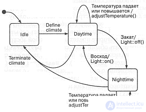
Fig. 5-20. State transition diagram for the greenhouse environmental controller (EnvironmentalController).
Example. Up to now we have introduced the icons that describe the essential elements of state transition diagrams. Together they provide the developer with a notation sufficient for modeling a simple flat finite state machine, suitable for describing applications with a limited number of states. Systems that have many states, or that possess highly convoluted event-driven behavior described by conditional transitions or by transitions resulting from previous states, require more advanced concepts for building transition diagrams.
Fig. 5-20 shows an example of the use of the essential notation. The example again describes the hydroponics system. We see a state transition diagram for the class EnvironmentalController, first introduced in Fig. 5-5.
On this diagram all events are represented by symbolic names. We see that all objects of this class begin their life in the initial state Idle; then they change their state upon the event Define climate, for which no explicit actions are assumed (it is taken that this event, that is, entering the climate assignment, occurs only during the daytime). Further, the dynamic behavior of this class consists of switching between the states Daytime and Nighttime; it is determined by the events Sunrise and Sunset respectively; actions that change the lighting are associated with these events. In both states, the event of a drop or rise in the greenhouse temperature triggers a compensating reaction (the operation adjustTemperature(), which is local to this class). We return to the state Idle when the event Terminate climate arrives, that is, when the climate assignment is canceled.
Advanced concepts
The elements of state transition diagrams that we have just described are insufficient for many cases of complex systems. For this reason we will extend our notation to include the semantics of statecharts proposed by Harel.
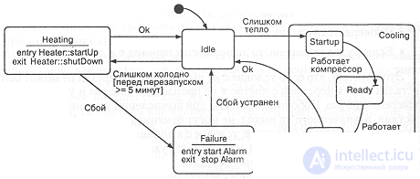
Fig. 5-21. Actions, conditional transitions and nested states.
Actions associated with states, and conditional transitions. As shown in Fig. 5-18, actions may be associated with states. In particular, one may assign the execution of some action on entry to or exit from a state, using the syntax of the following examples:
As with transitions, any action may be assigned after the keywords entry and exit(entry and exit).
An activity can be associated with a state using the syntax of the following example:
This syntax serves as shorthand for the explicit instruction: "Begin the activity on entry to the state and end it on exit from it".
In Fig. 5-21 we see an example of the use of this notation. On entry to the state Heating the operation Heater::startUp() is invoked, and on exit the operation Heater::shutDown(), that is, heating is started and stopped. On entry to and exit from the state Failure, the alarm signal is respectively raised and stopped (Alarm).
Consider also the transition from the state Idle to the state Heating. It is made if the temperature has dropped, but only in the case that more than five minutes have passed since the heater was last switched off. This is an example of a conditional (or guarded) transition; the condition is represented by a Boolean expression in brackets.
In general, each transition may be associated either with an event, or with an event and a condition. "Transitions without an event" are also allowed. In this case the transition is made immediately after the completion of the action associated with the state, and the action associated with exit from that state is also performed. If the transition is conditional, it takes place only if the condition is satisfied.
The order of execution of a conditional transition matters. Suppose there is a state S, from which, on event E, a transition T is made with condition C and action A. The transition T is carried out in the following sequence:
This means that if the condition C is not satisfied, then the transition cannot be carried out until the event E occurs once more and the condition C is checked once more. Side effects arising during the evaluation of the condition or the execution of the action assigned on exit cannot cancel the transition. For example, suppose the event E occurred, the condition C was satisfied, but the action A, performed on exit from the state S, changed the situation so that the condition C ceased to hold: the transition T took place all the same.
We may also use the following syntax:
Here the name of a state is used (which may be qualified). The expression is true if and only if the system is in the indicated state. Such conditions are especially useful when some outer state needs to trigger a transition on a condition involving some nested state.
One may also use in a condition an expression imposing timing constraints:
This condition is satisfied if the system has been in the state Heating for more than 30 seconds and remains in it at the moment of the check. This type of condition is used in real-time systems for "transitions without an event", since it protects the system from hanging for a long time in one state. This expression can be used to specify a lower bound on the time spent in a given state. If a timing constraint is applied to every transition with an event leading out of a given state, this will be equivalent to requiring that the system remain in each state for at least the time indicated in the constraint [Harel proposed a "generalized squiggle" to denote two-sided time bounds, but we will not discuss his generalizations here, since timeout conditions are expressive enough].
What happens if some event occurs but it is impossible to move to another state, either because no transition exists for the given event or because the transition's condition is not satisfied? By default this should be considered an error: ignoring events is usually a sign of an incomplete analysis of the problem. In general, for each state one should document the events that it deliberately ignores.
Nested states. The ability to nest states within one another gives depth to transition diagrams; this key feature of Harel's statecharts prevents the combinatorial explosion in the structure of states and transitions that often occurs in complex systems.
Fig. 5-21 shows the internal details of the state Cooling, that is, the states nested within it; for simplicity we have omitted all of its actions, including the entry and exit actions.
Enclosing states, such as Cooling, are called superstates, and nested ones, such as Running, are called substates. Nesting may go to any depth, that is, a substate may be a superstate for nested states of a lower level. The given superstate Cooling contains three substates. The semantics of nesting implies an xor (exclusive or) relationship for the nested states: if the system is in the state Cooling, then it is in exactly one of the substates Startup, Ready or Running.
To make it easier to find one's way around a transition diagram with nested states, we can zoom in or out relative to a chosen state. Zooming out makes the nested states disappear, and zooming in makes them appear. Transitions into substates hidden on the diagram and exits from them are shown by an arrow with a stub, like the transition into the state Ready in the figure [To be precise, the transitions Too hot and Ok relative to the state Cooling should also be shown in Fig. 5-21 with a stub, since these are transitions between substates].
Transitions between states are allowed to begin and end at any level. Let us consider the various forms of transitions:
History. Sometimes, when returning to a superstate, we would like to arrive at the substate we were in last time. We will depict these semantics with a history icon (the letter H (History) inside a circle placed somewhere within the superstate icon). For example, in Fig. 5-22 we see an expanded depiction of the state Failure. The very first time our system enters it, it takes the default initial state Create log; this is denoted by an unlabeled transition from the filled circle inside the enclosing state; once the log (log) has been created, the system moves to the state Log ready. After the failure message has been entered in the log, we return back. When we enter the state Failure the next time, we will not need to create the log again, and we will go straight to Log ready, since when we last left the state Failure, the system was in precisely that substate.
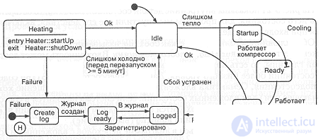
Fig. 5-22. History of events.
The effect of "history" extends only to the level at which it is indicated. If we want to extend its effect to all lower sublevels, we denote this by adding an asterisk to its icon. An intermediate result can be obtained by adding the history icon only to individual substates.
Specifications
Each element of a transition diagram may have a specification that gives its complete definition. Unlike class specifications, the specifications of transitions and states add nothing to what has already been described in this section, so there is no need to discuss them separately.

Comments