
Lecture
Sample-and-hold circuit (also sample-and-hold amplifier, S/H) in electronics — a circuit that stores the voltage present at its input at a given moment in time. It is a component of most analog-to-digital converters. The standard circuit for converting an analog signal into digital form involves sampling in time followed by quantization in level. Sampling in time is performed using sample-and-hold circuits (S/H), which during the sampling interval ( tracking) reproduce the input analog signal at the output, and when switched to hold mode retain the last value of the input voltage until the next sampling signal arrives, that is, in essence, they are analog memory devices. The stored signal ( the current time sample) is fed to an analog-to-digital converter (ADC) for conversion into digital form. For the ADC to operate correctly, the signal being converted must remain constant throughout the conversion time.
Since real ADCs cannot perform an analog-to-digital conversion instantaneously, the input analog value must be held constant, at least from the beginning to the end of the conversion process (this time interval is called the conversion time). This problem is solved by using a special circuit at the ADC input - a sample-and-hold circuit. The circuit holds the input voltage on a capacitor, which is connected to the input through an analog switch: when the switch closes, the input signal is sampled (the capacitor charges to the input voltage), and when it opens - the value is held. In microcontrollers, the ADC's sampling rate can be configured in software. However, the higher the rate (the more frequent the sampling) – the greater the conversion error (the lower the accuracy). This is how the joint operation of the ADC and the sample-and-hold circuit is achieved.
The circuit of the simplest S/H is shown in Fig. 10.10a.
When switch S is closed, the circuit's output voltage follows the input, that is VOUT = VIN (Fig. 10.10b). When the switch opens, VOUT retains the value corresponding to the moment of opening. The output op-amp follower prevents the holding capacitor CH from discharging into the circuit's load. The follower's input resistance should be as high as possible, so op-amps with FET inputs are usually used. This circuit, for example, is the basis of the SMP04/08 multichannel S/H devices made by Analog Devices.
S/H circuits are produced either as separate ICs or together with an ADC in a single chip.
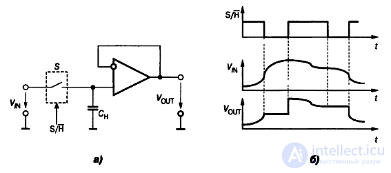
Fig. 10.10. Sample-and-hold circuit:
For the input voltage to remain as stable as possible, it is important that the capacitor have very low leakage and that it not be subjected to any significant loading, which requires a very high input impedance .
A sample-and-hold circuit can operate in one of two modes, depending on the voltage at the control input :
In tracking mode, the output signal of the sample-and-hold circuit matches the input signal. In hold mode, the voltage at the circuit's output is constant and equal to the voltage at its input at the moment it switched to hold mode.
A distinction is sometimes drawn between a sample-and-hold circuit (S/H) and a track-and-hold circuit (T/H). The only difference between them lies in how they are used: in the first case, the switch is closed for the minimum time needed to charge the capacitor; in the second case, the switch remains closed for a fairly long time .
For most analog-to-digital conversion circuits to operate correctly, requiring this most of all for successive-approximation ADCs, the input voltage must remain unchanged for a certain time, called the (conversion time). Since the input signal can change during the conversion time, it is held fixed using a sample-and-hold circuit.
Most often the sample-and-hold circuit is integrated on the same die as the ADC, but specialized ICs that perform this function also exist.

Comments