Lecture
Abstract: The interaction of nodes and devices of a classical three-address computer is considered at various stages of automatic program execution.
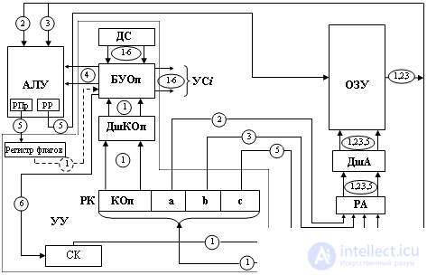
To improve the understanding of the issues of interaction between nodes and computer devices, consider the automatic command execution in a three-address computer with a classical architecture. The block diagram of such a computer is shown in Fig. 12.1

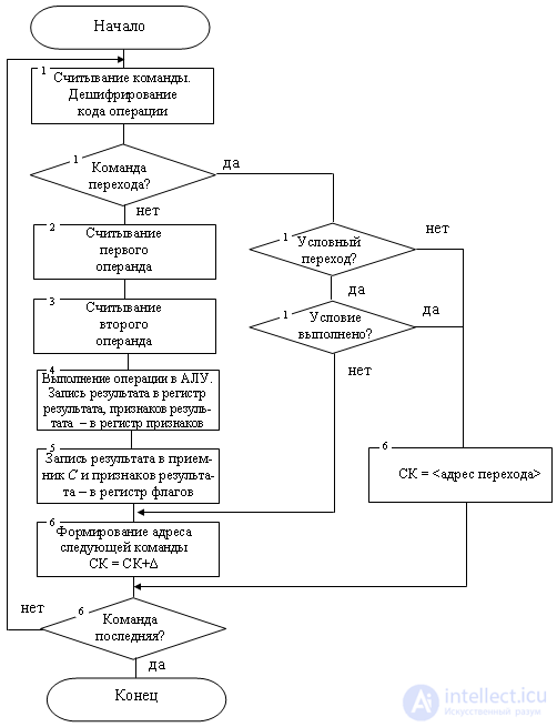
The processing of a command can be broken down into a number of functionally completed actions (steps) constituting its cycle (Fig. 12.2).

We will study the cycle of the team under the following initial conditions and assumptions:
Define the interaction of nodes and computer devices at each stage.
The first stage is the selection of the executable command from the RAM. To implement this stage, you need the code from the command counter (CK) = k to transfer to RAM, go to the RAM cell with address k and the contents of this cell, which is the code of this command, transfer to the command register. The corresponding gears are marked in fig. 12.1 digit 1: transfer of the code of the SC to the RA (address register) of RAM, address decryption on the address decoder (DSA), reading the command from the (k) RAM cell and sending it to the RK.
The address register is used to store the address where RAM is accessed for the duration of this request. The decoder transforms the address arriving at it into a unitary code that is directly perceived by the physical elements of the memory circuits. At its outputs there is always one and only one excited bus corresponding to the address of the selected cell. The register of instructions is intended for storing in the processor a command read from RAM for the time of its execution. At this stage, after receiving the command on the RK-decoder of the operation code (Dshkop), the operating part of the command being executed determines the type of command. The signal from DShKop in this way adjusts the operation control block (BOOP), that at its outputs control signals (DC i ) are generated, which are necessary for the automatic execution of the entire command cycle up to the entry of a new command in the RC. The formation of the CA i is based on the signals from the signal sensor (DS), which produces pulses evenly distributed over its outputs. The command register, the decoder of the operation code, the operation control unit, the signal sensor, the command counter constitute the control device.
If this command is not a transition command, then the following sequence of steps is implemented as a continuation of the first.
The second stage is the sampling of the first operand (a). It is necessary to transfer the code from the address field of the first operand - a from the RK to the RAM, access the cell with the address a in the RAM, and transfer the code of this cell to the ALU. The corresponding gears are marked in fig. 12.1 digit 2.
The third stage is the selection of the second operand (b). Produced by analogy with the second stage. The corresponding gear in fig. 12.1 marked with the number 3.
The fourth stage is the execution of the operation in accordance with the command operation code field. At the end of the first stage, the operations switch determined the type of command to be executed. Operands transferred to the ALU in the second and third stages. The operations control unit generates the control signals necessary to perform this operation in the ALU. The result of the operation performed in the ALU is stored in its internal result register (PP), and the signs of the result are stored in the ALU feature register. The corresponding transmissions and interactions of the blocks are indicated in fig. 12.1 digit 4.
The fifth stage is to access the RAM and write to the address c of the result of the operation. Here the code of the field c of the command register is transferred to the RAM in the RA. Then, the result of the operation in the result register of the ALU is written into the RAM cell with address c. Signs of the result are recorded from the register of signs of ALU in the register of computer flags, from which they are transmitted to the control unit, if the next command read by the MCR is a conditional branch command. The corresponding gears are marked in fig. 12.1 digit 5.
The sixth stage is the formation of the address of the RAM cell where the next program command is located, that is, the replacement of the old code in the command counter with a new one. Since the computer assumes the natural order of program execution, the next command is located in the RAM cells located immediately after the cells occupied by the executed command. Considering that the executed command is in memory  cells, we get that the essence of this stage is the following change in the command counter:
  . This ends the command execution cycle: the following command address is generated in the SC
  . The implementation of this stage can be combined with the implementation of the previous stages, which is implemented in most computers.
The given sequence of stages is repeated further for each of the subsequent commands of the program, which ensures automatic execution of the program.
When executing a transition command, the above sequence of steps changes. For example, at the end of the first stage, the code decoder of the operation code recorded the execution of the unconditional jump command. This situation can be represented as: (k) = BP j, that is, the code of the command being executed is selected from the cell with address k, this is an unconditional branch command (BP) that must transfer control to the execution of a command that has an offset j relative to the current command. In this case, the execution of stages from the second to the fourth is blocked, and the execution of the unconditional jump command consists in adding the value of j to the command counter.
In a conditional transition command, the violation of the natural order of program execution (that is, the transfer of the k + j code to the SC) occurs only when a certain condition is met. This condition characterizes the result obtained by the command preceding the conditional jump command.
Such a condition may be, for example, a negative result or a result equal to zero.
Comments
To leave a comment
Digital devices. Microprocessors and microcontrollers. computer operating principles
Terms: Digital devices. Microprocessors and microcontrollers. computer operating principles