Lecture
Comparator
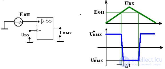
A comparator is a device designed to compare the measured input signal Uvh with the reference voltage Uop.
Voltage comparators are called ICs, designed to compare two voltages and output the comparison result in a logical form: high signal level, low signal level

There are three types of comparators:
• High-speed Δt ≤ 1nsec
• Average 1nsec ≤ Δt ≤ 10nsec
• Slow Δt ≥ 10nsec
Digital comparators (compare from English compare) compare two numbers A, B of the same bit size, set in binary or binary decimal code. Depending on the circuit design, comparators can determine the equality A = B or the inequalities A B. The comparison result is displayed as a logical signal on the outputs of the same name.
Digital comparators are used to identify the desired number (word) in digital sequences, to mark the time in watch devices, to perform conditional transitions in computing devices, as well as in address selectors [18].
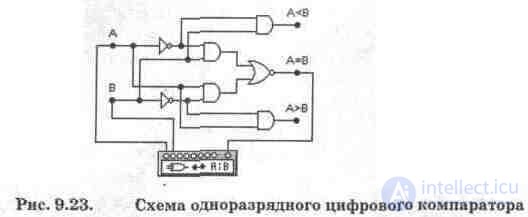
A single-digit comparator circuit is shown in Fig. 9.23. The comparator consists of two NOT elements, four AND elements, and one OR-NOT element.

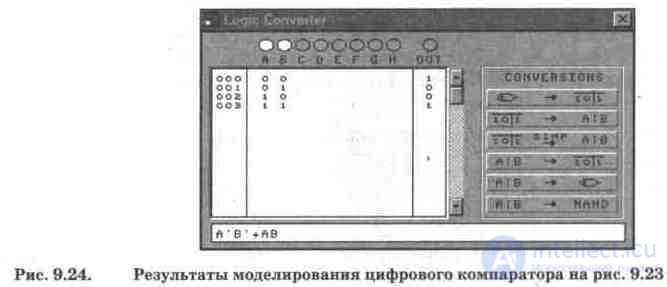
To study the comparator, a logic converter is connected to it. By connecting its OUT terminal to each output of the comparator, you can get a truth table and a Boolean expression for each mode of operation of the comparator. For case A = B, shown in Fig. 9.23, the simulation results are presented in Fig. 9.24, which shows that condition A = B corresponds to two combinations of signals at the input: A = B = 1 or A = B = 0. This condition meets the Boolean expression on the secondary display.

Test questions and tasks
1. What functions does the digital comparator perform, in which devices can it be used?
2. Using the circuit in fig. 9.23, conduct its research in modes A> B, A
Comments
To leave a comment
Digital devices. Microprocessors and microcontrollers. computer operating principles
Terms: Digital devices. Microprocessors and microcontrollers. computer operating principles