Lecture
Abstract: The classical foundations of the construction of a computer (Turing machine, the element and Neumann automaton), the principles of Neumann of the construction of a computer, the structure of a classical computer are considered.
The foundations of the construction of electronic computers in their modern sense were laid in the 30s-40s of the last century by prominent scientists: the English mathematician Alan Turing and an American of Hungarian origin, John (Janos) Neumann.
In 1936, A. Turing formulated the concept of an abstract computer. Simultaneously with him, although not in such an explicit form, E. Post (USA) did the same. Although the Turing machine (MT) has not become a real operating device, it has until now been constantly used as the main model for clarifying the essence of such concepts as “computational process”, “algorithm”, and also for clarifying the connection between the algorithm and computers [11 ].
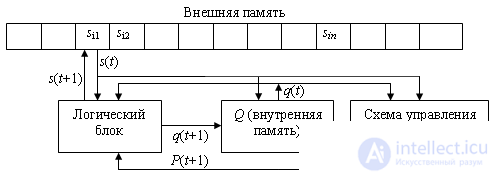
The Turing machine (Fig.10.1) has a finite number of characters s i , forming an external alphabet , in which the information supplied to the MT, as well as generated in it, is encoded. Among the signs there is an empty sign (s 1 ), the parcel of which in any cell erases the sign that was in it and leaves it empty.

Depending on the submitted initial information  (contained on the tape of external memory characters) two cases are possible:
 ), giving a signal to stop. In this case, the MT is applicable to the information.
  and processes it into information
  ;
; 
At each moment only one cell of the tape (memory) is viewed. The transition can be carried out only to the neighboring cell (R - to the right, L - to the left, N - no transition (to remain)). The transition to an arbitrary cell is performed by successively iterating over all the cells separating the current and necessary cells. On each individual cycle t, the command prescribes only the replacement of the only sign s i , stored in the monitored cell, with some other sign s j .
The logical block MT has a finite number of states {q i } i = 1..m.
The characters R, L, N, q 1 , .., q m form the inner alphabet of the machine.
Recycled sign s j recorded in the viewed cell, the state that the Turing machine will take in the next cycle q (t + 1) and the transition to the next cell P (t + 1) performed in this cycle are a function of the character analyzed in this cycle and the current state machines s i and q (t):
The program for MT is determined by the triple {s i , P, q} t .
An example of writing a program for calculating the logic function "disparity" for the Turing machine is presented below.
| Symbol (s i ) | condition | |||
|---|---|---|---|---|
| q1 | q2 | q3 | q4 | |
| 0 | 0, R, q2 | 0, N, q4 | 1, N, q4 | 0, N, q4 |
| one | 1, R, q3 | 1, N, q4 | 0, N, q4 | 1, N, q4 |
Before starting work, the Turing machine is in the q1 state of reading the first operand.
This MT is applicable to the source information. Stop - state q4. The value of s i in the cell y does not change (the result is saved).
If the program for MT will be determined by the transition table
| Symbol (s i ) | condition | |||
|---|---|---|---|---|
| q1 | q2 | q3 | q4 | |
| 0 | 0, R, q2 | 0, N, q4 | 1, N, q4 | 1, N, q4 |
| one | 1, R, q3 | 1, N, q4 | 0, N, q4 | 0, N, q4 |
then this MT will not be applicable to the initial information, since in the q4 state the value of s i in the cell y is constantly changing to the opposite.
According to the principle of information processing, the computing device proposed by Neumann (Neumann automaton - AN) differs significantly from the Turing machine.
An important feature of the Turing machine is that the transformation of information on each cycle occurs only in one cell, the others wait for a visit to the head, although it is often possible to work in parallel.
The simplest solution is to use several Turing machines with a common external memory (tape) for them - it is not always permissible due to possible conflicts when accessing the same memory cell.
In the Neumann machine, the number of simultaneously processed cells can grow indefinitely, remaining finite at each moment.
The Neumann element (EN) is a device that resides in one of a finite number of states on each clock cycle.  forming his alphabet. EN has two input channels: left and right; for each of them, at the time t, one of the states from R also arrives (Fig. 2).

The element implements the function  , that is, in the t + 1 cycle, it enters the z state, determined by its state at the current time and the values received on the input channels.
The states of the Neumann elements at time t determine the configuration of the Neumann automaton (Fig. 3) at time t: K (t).

The functioning of AH is the transition from the state K (t) to the states K (t + 1), K (t + 2) ...
In a single cycle, a large number of Neumann elements can change their state, which in fact leads to parallel processing of information.
In 1946, at the summer session of the University of Pennsylvania, John Neumann distributed a report that laid the foundation for the development of computing technology for several decades to come. The subsequent development experience of the computer showed the correctness of the main findings of Neumann, which, naturally, in subsequent years, developed and refined.
The main recommendations proposed by Neumann for computer developers [11]:
The program as well as the numbers with which the machine operates, is represented in binary code. Thus, according to the form of presentation, teams and numbers are of the same type. This circumstance leads to the following important consequences:
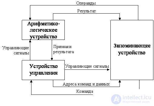
A computer built according to the principles defined by Neumann consists of the following main blocks (Fig. 4): a storage device, an arithmetic logic unit and a control device.

A memory device, or memory, is a collection of cells designed to store some code. Each cell is assigned a number, called an address . The information recorded in the cell can be both computer commands and data.
A machine command is a binary code that determines the operation to be performed, the addresses of the operands used, and the address of the memory cell in which the result of the operation must be recorded.
The operations determined by the operation code of the command are performed in the arithmetic logic unit (ALU).
All actions in the computer are performed under the control of signals generated by the control unit (CU). Control signals are generated based on the information contained in the command being executed and the result attributes generated by the previous command (if the command being executed is, for example, a conditional branch command). In addition to the signals that determine certain actions in various computer units (for example, the type of operation in the ALU or the read signal from the memory), the control unit also generates the addresses of the cells that are used to access the memory to read the command and operands and record the result of the command.
The control unit generates the address of the command to be executed in this cycle, and outputs a control signal to read the contents of the corresponding cell of the storage device. The read command is transmitted to the control unit. According to the information contained in the address fields of the command, the CU generates the addresses of the operands and control signals for reading them from the memory and transmitting the vari-metric-logical device. After reading the operands, the control unit according to the operation code contained in the command issues signals to the ALU to perform the operation. The result obtained is recorded in the memory at the address of the result receiver under the control of the recording signals. Signs of the result (sign, presence of overflow, sign of zero, and so on) go to the control unit, where they are written to a special register of signs. This information can be used when executing the following program commands, for example conditional jump commands.
Comments
To leave a comment
Digital devices. Microprocessors and microcontrollers. computer operating principles
Terms: Digital devices. Microprocessors and microcontrollers. computer operating principles