- * a section of optics that studies physical phenomena that occur and occur in optical fibers, or
- * products of the industries of precision engineering, having in its composition components based on optical fibers.
Fiber-optic devices include lasers, amplifiers, multiplexers, demultiplexers and a number of others. Fiber-optic components include insulators, mirrors, connectors, splitters, etc. The basis of a fiber-optic device is its optical scheme - a set of fiber-optic components connected in a specific sequence. Optical circuits can be closed or open, with or without feedback.
Main problems of fiber-optic communication lines (FOCL)
Signal attenuation – caused by bends, connections, poor-quality welding.
Dispersion (chromatic, polarization) – distorts the signal, reduces throughput.
Mechanical damage – breaks, microcracks due to external factors.
Contamination of connectors – dust, grease, moisture worsen transmission.
Reflection and scattering – affects the quality of the signal, leads to losses.
Diagnostic and testing methods of FOCL
- Reflectometry (OTDR) – reveals attenuation, damage, welding spots.
- Signal level measurement – checking the power with an optical meter.
- Spectral analysis – assessing dispersion and losses at different wavelengths.
- Checking connections and connectors – cleaning and quality control of optical connectors.
- Load testing – checking the network’s performance in real conditions.
Problem solving
- Use of high-quality fibers and correct welding techniques.
- Minimization of bends and mechanical loads.
- Regular maintenance, cleaning of connectors.
- Use of amplifiers and dispersion compensators.
- Continuous monitoring and diagnostics using modern devices.
These measures help maintain stable and reliable operation of the fiber-optic communication line.
The emergence of fiber-optic telecommunication technology puts forward new and new problems that are primarily systemic or related to the specific specifics of operating conditions. The operation of Siberian fiber-optic communication lines (FOCL) is no exception.
The construction of the BOJIC) revealed a number of unique problems that have not yet been encountered in other countries, and in western regions, the specificity determined the feasibility of installing the fiber optic cable in the lightning cable of power lines (LEP), which, in turn, necessitates the use of fibers at temperatures from (-60 ° С) to (+ 50 ° С) The need to overcome large non-inhabited spaces also forces to exploit areas up to 180km long. The use of ready-made fiber optic sections revealed, for example, an increase in atuhaniya fiber optic medium interposed in grozotrosse due to cyclical temperature effects on the end portions of cable couplings. Other problems are thunderstorm, seismic and wind effects on the reliability of fiber optic communication, electro erosion of fiber shells near high-voltage wires, defect formation at the fiber junction under the influence of permafrost. The solution of the problem of diagnosing remote fiber optic channels from the central control room
It can be assumed that the further development of fiber optic links and the solution of these problems will be associated with the extensive use of computer optics methods and tools and the use of elements of diffraction optics in all cascades of a fiber communication channel.
The purpose of this work is the preliminary formulation of some problems of operation, testing and diagnostics of fiber optic links on the example of the Siberian areas, laid in the power lines of the transmission lines.
In optical cables with free installation of modules as a result of operation at low temperatures, due to the difference in thermal expansion coefficients of the metal and fiber parts (respectively 12.9 ■ 10 "BC" 1 and S-IO ^ C'1), the process of longitudinal compression of fiber modules In this case, the modules (in the ideal case) are arranged in a spiral. For a cable with a cross section of 60 mm *, this spiral has the following parameters: diameter - 1 mm, twist pitch ~ 8 cm. Therefore, it is clear that when the temperature drops, in addition to axially symmetric compression caused by shrinkage ozhnoy crystallization of polymeric membranes and the gel filler optical module that changes a numerical aperture of the fiber, besides its own quartz thermal compression, act on the fiber compressive forces in the longitudinal and transverse directions
Calculating the length of the cable in the span, taking into account changes sag [1]:
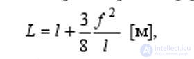
where I is the required cable length, 1 is the span length, f is the sag arrow, we get 1_30 = 450.424 m, 1 + 30 = 450.746 m => D1 = 0.322 m, where DL is the change in the length of the kaoel in one flight, i.e. technological length of 4.5 km, the difference in length at critical temperatures is ~ 3 m, which causes compression of the optical modules and, as a consequence, can change the optical characteristics of the fiber
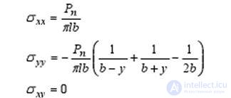
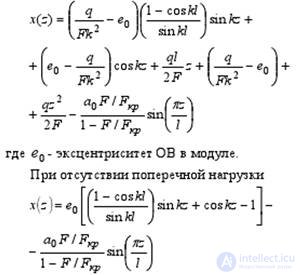
The exact solution of the problem of changing the properties of an optical fiber (OM) is reduced to finding the stress tensors with unilateral transverse compression with a longitudinal-transverse load. Since it is not yet possible to comprehensively consider this issue, consider the listed loads separately.
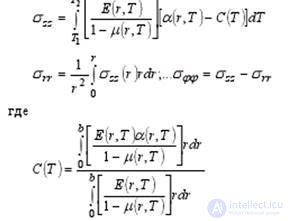
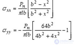
Suppose that forces acting in the same plane are applied to the fiber, and the bending radius of the optical fiber is sufficiently large. Then the components of the stress tensor can be represented as follows [2]:
- for points lying on the x axis (y = 0)
- for points lying on the axis (x = 0)
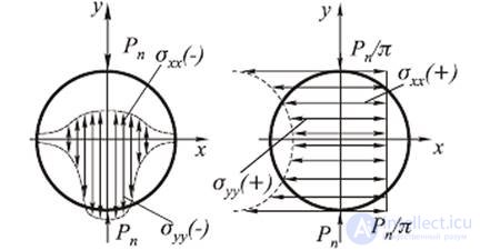
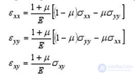 Fig.1. Stress plots with transverse compression of the fiber a on the x, b axis on the y axis; (the signs "+" and "-" mean, respectively, tension and compression) As can be seen from the figure, the stress field in the fiber has a complex structure. Using the components obtained, we can obtain the dielectric constant tensor, which shows that the fiber becomes anisotropic
When radiation propagates through an anisotropic fiber [2], two orthogonally polarized waves may appear. This is one of the reasons for the broadening of a pulse with applied mechanical loads, since Optical anisotropy causes a difference in the constant propagation of polarized waves, the polarization planes of which are differently oriented relative to the applied vultures. Experimental studies show [2] that with one-sided transverse compression, the attenuation
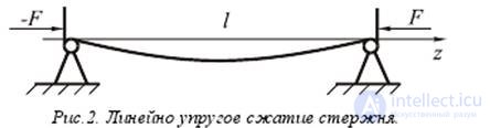
Consider the issue of the emergence of a longitudinal-transverse load during the heat shrinking of the cable elements. Due to the small / cross section of the cable tube (in which the S are located) in comparison with its length, the effect of heat shrinkings can be analyzed using the example of linearly elastic longitudinal compression of the rod (Fig. 2)
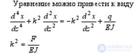
Equilibrium equation of the rod in the deformed state is
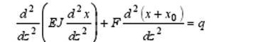
where F is the longitudinal compressive force, q is a transversely distributed load, which can also cause a deflection of the wire, x0 is the initial deflection of the fiber.
where E is Young's modulus is the moment of inertia
fiber radius b. The general solution of the equilibrium equation will be
where is the critical Eulerian vulture, a0 -
bend amplitude. Approximate longitudinal force can be calculated by the formula
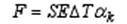
where S is the cross-sectional area of the cable, E is the elastic modulus of the cable, DG is the temperature difference, the coefficient of thermal expansion of the metal part of the cable. From (S) we find R ~ 0,63 kg
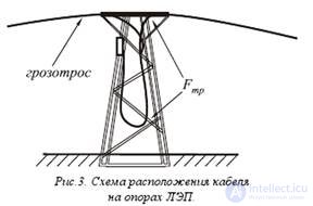 It should be noted that such a statement of the problem (longitudinal compression of the rod with fixed ends) is valid because the fiber-optic modules are held at the vanishing points in the cable by friction force Fmp (Fig. 3), otherwise the modules would go out into the coupling.
During operation, the cable undergoes cyclic loads [4] when the wind pressure and temperature change, which leads to the imposition of cola *** of different wavelengths and amplitudes (Fig. 4). If, due to the smallness of the laying diameter of an OB cable, it can be considered a string, then these oscillations are: the standing wave of the fiber bundle itself, cable own vibrations *** (vibration) with wavelength A. -10 mA amplitude A ~ 3 mm; periodic wind loads causing oscillations with length in lengths of X-2L m and amplitude up to A ~ 1 m
| |
| |
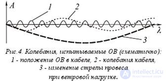 |
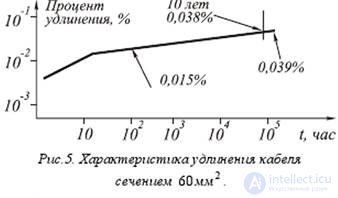
Such a cyclical change in the load on the OS most likely leads to a smooth degradation of the waveguide, the speed of which, so far, cannot be established. It is also necessary to take into account the fact that, due to inelastic cable stretching, the annual compressive loads on the fiber will decrease, as shown in Fig. 5, (according to Fujikura Ltd [5] calculations, after 10 years the cable elongation will be 0.038%, te for length 4 , 5 km it will be -1.7 kf, but this will lead to an increase in tensile load
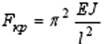
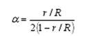 We present the calculations of the critical bending radii for the OF and the heat shrinkage ratio of the metal part of the cable. The relationship for the heat shrinkage coefficient, tube diameter and bending radius is [2]
 where a. - the coefficient of thermal shrinkage of the cable, g - the inner tube, R - the radius of the bend of the Minimum bend radius of the bend
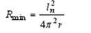
where ln is the bending period of the OB after the completion of the shrinkage process
From [b] for S, the minimum bending radius is ~ 3, b cm for module S — 7.2 cm free run of the harness. S modules ~ 1 mm (g = 0.5 mm) From (8) we find a ^ x for OKGT, it is = 0.003, m for L = 4.5 km D1 = 13.5. \ {In real * conditions a = 7.3 44, that is D1 = 3.5 liters. From (9) we find the minimum laying period of the OB /, 1Jnm = 3.8 cm, but in reality it is three times longer
As noted above, the ambient temperature directly affects the transmission characteristics of the signal in the optical fiber.
 First of all, a change in temperature is affected by a change in the refractive index
Temperature dependence of the refractive index leads to a time delay of the radiation pulse propagating through the fiber. Another mechanism of temperature influence on the transfer characteristics of a fiber is the occurrence of thermal stresses in the fiber, in which the polymer shell has a higher solidification temperature than the core. Thermal stresses are associated with the elastic properties of the fiber materials, temperature dependent, and the thermal expansion coefficient of these materials as follows at once
These stresses cause a change in the numerical aperture of ~ 4% in a gradient light guide.
Thus, even the use of the standard for power transmission lines of the methods for estimating mechanical quantities shows that BOJIC can be extremely difficult to operate. It should be noted that the question of the influence on the transmission quality of optical signals of fatigue processes in glass, or rather, in a thin fiber, in which the properties of glass may differ significantly from the characteristics of massive samples, remains unexplored.
Technological problems of optical fibers
Optical fiber and cable are fairly new industrial products and their operational quality is therefore far from the parameters of conventional electrical products. Along with the standard requirements for minimizing signal attenuation at BOJIC and fiber joining sites, increasing the efficiency of radiation input and output, etc., during system operation in the harsh continental climate of Eastern Siberia, the “fiber extrusion” defect in the docking sleeves came to the first place.
A characteristic feature of a sharply continental climate is the presence of large temperature daily coli *** *** up to 20 degrees With the arrangement of optical fibers in a ground wire, the range of daily coli *** can reach 40 degrees due to radiant solar heating of the cable and couplings. It can be assumed that the main reason for the "extrusion" of fibers from the shell is the strong difference between the coefficient of thermal expansion of the plastic sheath of the optical module (OM) and the parameters of optical fibers (OM). With great certainty, it can be argued that during the manufacture of the cable, modification of the polymer to ensure frost resistance was carried out without additional measures to stabilize the performance properties of the polymer. Therefore, when operating under the effect of daily temperature ranges *** after 1-2 months, there is a significant extension of fibers from the sheath - up to 50 mm. The extrusion process is due to the mechano-thermal destruction of the polymer and is irreversible. After the end of the main stage of destruction (after about 3 months), the polymer goes into a stage of physical and chemical aging. In actual operation, the cyclic thermal destruction of the polymer is aggravated *** by constant OM microvibrations transmitted from the ground wire hanging between the supports.
The "extrusion" of an explosive occurs by the mechanism of the "ratchet wheel" and is initiated by the movement of the OM sheath, and the fixation of the extended fiber relative to the sheath occurs on the turns of the spiral coiling of the explosive around the power element OM. Therefore, temperature fluctuations in winter and summer will cause further development of this defect. Considering the possible considerable radiant heating of the couplings in the summer period, it is possible to assume the amplification of this defect in the summer. The "extrusion" of fibers from OM is of a statistical nature and therefore it can be argued that those OM and couplings in which this defect is still missing will deteriorate somewhat later.
To suppress the defect as a first step, reassembly of the connections in couplings is now undertaken, and then the design of the couplings will be reworked with the replacement of a rectangular cassette with a round one with a spiral styling of fiber, providing spatial reserve for the location of the extruded sections without undesirable bends. In order to completely eliminate the defect, it is necessary to use a polymer in the manufacture of the cable, which is subjected to structural stabilization using known technological methods (PC, UV irradiation, microwave heating, the introduction of chemical stabilizer additives, etc.). Of course, it is necessary to carry out appropriate tests in Siberia. conditions.
On the whole, the arisen defect of “extrusion” of an explosive appears to be very significant and drastically reducing the operational reliability of the entire line. It will require, if it is not removed, the constant carrying out of a significant amount of repair work.
Problems of diagnosis and testing BOJIC
At present, optical reflectometers are used to check the quality of communication lines [7]. They use in their work the principle of reverse Rayleigh scattering. Information on the results of the sounding of the line is displayed in the form of a reflectogram showing the change in attenuation depending on the length of the line. For analysis, a computer approximation of a large number of probe pulses is used. The practice of working with reflectometers from various manufacturers revealed a number of shortcomings of these truly remarkable expensive instruments.
Before starting work, the operator must enter the length of the probe pulse, which is necessary for a detailed study of a certain part of the route. To view and analyze short lines or nearby BOJIC areas and splices, it is necessary to measure at the shortest possible duration of the probe pulse (“Junsek”), while, however, the far end of the line will be “noisy” and will not be analyzed. When testing a remote part of the route and / or the whole line, long probe pulses must be used, but then the beginning of the route is in a “dead zone”, in which it is impossible to evaluate processes at the near end of the line, and there is also a “blurring” of non-uniformity of the welded joint visible on the trace. , which complicates the accuracy of determining its location. To solve this problem, it is desirable to develop methods for forming reference or reference points directly on the fiber, so that during the measurement it would be possible to “bind” to a specific geographic location.
When analyzing reflectograms, the meter periodically encounters imaginary irregularities that do not really exist on the fiber - these are so-called phantoms (Fig. 6), caused by re-reflections or other factors, possibly related to the nuances of information processing by the microprocessor. We can offer the following classification of such phantoms:
| |
| |
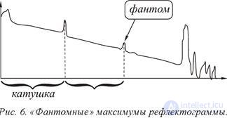 |
Phantom "Mirror twin". This phantom is often encountered when using a measuring coil (mainly at the BOJIC input control) and appears at a distance equal to the length of the measuring coil from the burst at the junction of the coil with the line (Fig. 6). The mirror twin "appears as a result of the Fresnel reflection from the mechanical connector at the junction of the measuring coil with the line. This phantom, despite the imaginary reflection (which can be taken as a microcrack), does not contribute to any attenuation. The effect is seen on the reflectometers of different companies. The similar phantom is known more on "metal" reflectometers of type P5-10. When this phantom appears, it is recommended to add a drop of immersion liquid to the junction of the coil with the line.
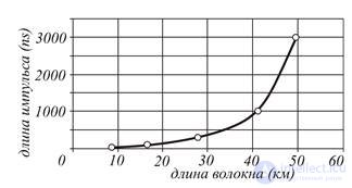
Phantom "Peak". This phantom is detected when measuring a BOJIC length of up to 70 km with a Wavetek Hellion reflectometer. It looks like a phantom peak, jumping up and down. It is extremely rare, the reason for its appearance is still unknown (possibly due to reflection from the end of the line). Cases of the disappearance of this phantom when bending the end or wetting the connector with an immersion liquid have been observed.
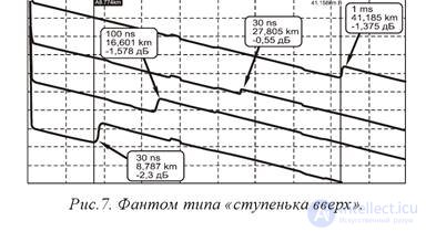
Phantom "Step up". It is observed quite rarely. For the first time, we have seen in the area 168.096 km long, on one fiber out of 16, when measuring HP Е6008 (Fig.7). The phantom is characterized by a supernaturally large amplitude - up to -2.3 dB - and appears at different distances, depending on the pulse length (see Fig.7 and Fig.8). When the “Step Up” phantom appears, it is recommended to measure at other pulse lengths or repeat the measurement with another device.
| |
|
|
|
| |
 |
| |
|
 |
| |
Thus, it is clear that many problems arise due to the use in the measurement of probe pulses with a fixed duration. Therefore, it seems promising to develop reflectometers with automatically changing probe pulses, which will allow, by fitting reflectograms at different pulse durations, to get rid of both “dead zones” and “noisiness” of remote areas, as well as help identify phantoms like “Peak” and “Step up” ". Along with this, it is necessary to create an algorithm for processing reflectograms, which would remove phantoms moving along the length of the fiber when the duration of the pulses changes, from the resulting trace. Automatic removal of the mirror twin phantom is also necessary.
Software tools available in real samples of reflectometers for processing the results of probing are far from perfect and therefore are practically not used in practice. This is due, for example, to inaccurate determination of the location of welded joints, omission of joints with “zero” attenuation, as well as inaccurate determination of the attenuation value itself. The so-called method of bilateral analysis of reflectograms cannot be considered effective. Therefore, the improvement of programs for processing reflectograms and algorithms for the operation of such devices seems to be a promising and relevant activity.
The development of the new principles of diagnostics and testing by BOJIC does not lose its relevance, but, on the contrary, is becoming more and more practical. The tasks of detecting non-localized defects and controlling mechanical-thermal stresses in the fiber are put in the forefront. Recently, new devices have been proposed that work on the principle of registration of Brillian scattering [8]. Brüllien reflectometers (BOTDR), unlike their usual predecessors, will allow to determine the fiber tension depending on the fiber length. With their help, it will be possible to identify areas with increased tension that require replacement due to an increased risk of microcracks. It should also be noted that currently, only temporal modulation of the optical signal is used to diagnose fiber-optic channels, which does not allow obtaining information on the state of the substance over the fiber section. The use of spatial modulation of radiation introduced into the fiber by means of diffractive optical elements — ideally tunable by control electrical pulses — would improve the quality of such measurements.
Along with fiber optic problems, there are common problems for fiber optics such as nonlinear effects in optical fibers. Nonlinear effects in an optical fiber are due to the nonlinear response of a substance to an increase in the intensity of the light flux. As a result, the optical characteristics of the medium (electronic polarizability, refractive index, absorption coefficient) become functions of the electric field intensity of the light wave, so that the polarization of the medium begins to depend nonlinearly on the field strength, and waves with different frequencies and directions of propagation influence each other. The main nonlinear phenomena characteristic of optical fibers: nonlinear refraction, stimulated scattering, and four-wave mixing. Nonlinear refraction is caused by the dependence of the refractive index of the fiber core (Kerr effect), and hence the phase of the output signal on the optical signal intensity. When the signal power is high enough, its collocations *** lead to phase self-modulation and phase cross-modulation (FCM). In the first case, the signal acts on itself, in the second - on the signal in another channel. Each of these effects can interfere with transmissions using phase shift keying. The maximum allowable value of channel power due to FSM and FCM is inversely proportional to the number of multiplexed channels. The nonlinearity of the refractive index in the dispersing medium of the fiber can lead to the formation of optical solitons. The use of optical solitons allows transmitting a signal over distances up to several thousand kilometers without distortion of the pulse shape, therefore communication lines using soliton transmission modes are promising, but today such systems are too expensive and do not find commercial use. Forced light scattering is scattering by elementary excitations of the medium induced by the scattered wave. Since the scattering process is stimulated by the scattered light itself, the scattered radiation is characterized by a high degree of coherence, narrow radiation patterns of individual components, and an intensity comparable to the intensity of the incident light. Thus, when a medium is excited by a powerful light source, its parameters are modulated, which leads to amplitude modulation of the scattered light and, consequently, to the appearance of new spectral components in it. The most important types of the phenomenon under consideration are: stimulated Raman scattering (WRC), also traditionally referred to as Raman anglophone sources, and Mandel'shtam-Brillouin stimulated scattering (SBS). SRS is associated with the excitation of new oscillatory and, to a lesser extent, rotational energy levels of particles of the medium, and SBS with the appearance of hypersonic waves in the medium. The effect of WRC is small (less than 1 dB per channel) and increases with the increase of the product of the total channel power and the difference between the frequencies of the extreme channels. In other words, this effect is significant only for systems with hundreds of channels. Unlike WRC, radiation scattered by the Mandel'shtam-Brillouin mechanism propagates only in the direction opposite to the incident one. Its intensity is significantly higher than with WRC. The effect of Mandel'shtam-Brillouin scattering depends on the transmission rate. With the growth of the latter, it decreases, and especially quickly when using phase manipulation. It can be neglected for pulses shorter than 10 ns. Four-wave mixing consists in the fact that in the presence of two waves with frequencies f1 and f2 (f1
Conclusion
It is currently difficult to find a field of science and technology where lasers would not be used. Generation was obtained for more than 1000 objects: crystals, activated glasses, liquids, semiconductors, plasma, gases. However, despite the well-known successes achieved in quantum electronics, in most cases the physical limits of the applicability of the basic principles underlying the operation of quantum devices have not yet been established. The limits of monochromaticity and coherence of the radiation and their connection with the power and frequency of the radiation are not clarified, it is not known how far one can go to the high-frequency region; what is the limiting value of efficiency when converting various forms of energy into coherent light, etc. By now, quantum generators have gone out of the field of academic research and have become the equipment of technical progress and instruments of scientific research. The development and improvement of quantum generators continues, new frequency ranges are mastered, the stability of all parameters is improved, power is increased.
In cases with fiber-optic systems, the data presented show that the task of creating reliable fiber-optic systems for telecommunication systems is still far from its final decision. The problems arising from the actual operation of the BOJIC require not only technological, but also fundamental research. A decisive contribution to the solution of these problems can be expected from the application of methods of computer and integrated micro-optics, which, in turn, can contribute to the development of new approaches in these areas of science and technology
Principles of laser technology
The induced laser radiation in quantum devices is the result of transformed mechanical, chemical, electrical, ionic and molecular energy into induced radiation. Induced radiation is the result of the interaction of the inoculated induced radiation with excited particles of the active element of a laser, where ions, electrons and molecules are used as particles.
The interaction of particles is described by the laws of thermodynamics. At thermodynamic equilibrium, the distribution of particles is described by the Boltzmann law in which the degeneracy coefficients, which characterize the degree of quantum yield under the action of the excitation energy. The number of excited particles depends on the type of material.
Under certain conditions, the system is in the excited state and when the particles move from the upper level to the lower level, radiation occurs:.
To obtain the mode of induced radiation, it is necessary to create an inversion, that is, an excess of particles at a higher level, for which it is necessary to create an excitation energy. With induced excitation of the upper level will be greater than the lower, and their difference is called inversion
Conclusion: In thermodynamics, the system is balanced, that is, in a induced radiation otherwise.
To obtain induced radiation, it is necessary that all particles from the upper energy level simultaneously pass to the lower energy level with a certain probability.


Comments
To leave a comment
Quantum electronics
Terms: Quantum electronics