
Lecture
A control system is a systematized (strictly defined) set of means for controlling a supervised object (the controlled object): possibly for collecting readings of its state, as well as means of acting on its behavior, intended to achieve specified goals. The object of a control system may be either a technical object or a human being. The object of a control system may consist of other objects, which may have a permanent structure of interconnections.
A control system controls, commands, directs or regulates the behavior of other devices or systems by means of control loops. It can range from a simple home heating controller with a thermostat operating a domestic boiler to large industrial control systems used to control processes or machines.
For continuously modulated control, a feedback controller is used to control a process or an operation automatically. The control system compares the value or state of the regulated process variable (PV) with the desired value, or setpoint (SP), and applies the difference as a control signal to bring the plant's process output to the same value as the setpoint.
For sequential and combinational logic, program logic is used, for example in a programmable logic controller.
Automatic control is a process in which the action on a plant or a device is achieved by means of control (command) signals. A characteristic feature of the control process is the open path along which the corresponding pulses travel.
The signals sent by the controlling device act on the machine or plant without ongoing recording and correction of the control process (Figure 1). Thus, in feed control the machine table is moved by a drive. The setting (regulating, controlling) signal in this case is the voltage UM applied to the feed motor. Together with the machine table, the motor forms what is known as the controlled object. The parameter to be controlled here is the feed path s that the table of this machine must traverse.
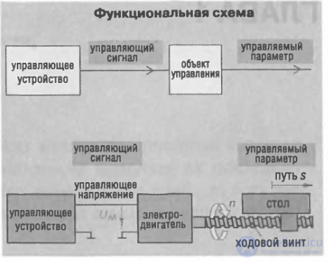
Figure 1. The principle of control, illustrated by a feed mechanism.
The term "controlling system" refers to the installation as a whole, in which the control process itself takes place. A functional diagram, which uses conventional symbols for the elements and lines for the functional links, gives a clear picture of how the individual control blocks interact. The direction of the control action is shown by arrows.
An information and control system (ICS) is a digital system for monitoring or controlling some real object.
General-purpose computing systems (CS) solve tasks that do not involve the need to make decisions in real time (computation, modeling, office tasks). All the remaining tasks fall within the domain of ICSs. Although this division of tasks is fairly arbitrary, ICSs that solve different tasks have clearly pronounced specific features.
A technical control structure is a device or a set of devices for manipulating the behavior of other devices or systems.
The controlled object may be any dynamic system or a model of one. The state of an object is characterized by certain quantitative values that change over time, that is, by state variables. In natural processes such variables may be temperature, the concentration of a particular substance in an organism, a securities price, and so on. For technical objects they are mechanical displacements (angular or linear) and their velocity, electrical variables, temperatures, and so on. The analysis and synthesis of control systems is carried out by the methods of a special branch of mathematics — control theory.
Control structures are divided into two large classes:
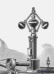
An automatic control system consists, as a rule, of two main elements — the controlled object and the controlling device.
Controlled object — a change in the state of the object in accordance with a prescribed control law. Such a change occurs as a result of external factors, for example as a result of control or disturbance actions.
These are able to maintain the extreme value of some criterion (for example, the minimum or the maximum) that characterizes the quality of operation of the given object. The quality criterion, which is usually called the objective function, the extremum index or the extremal characteristic, may be either a directly measured physical quantity (for example, temperature, current, voltage, humidity, pressure) or efficiency, productivity, etc.
The following are distinguished:
These serve to ensure the desired quality of the process over a wide range of variation in the characteristics of the controlled objects and of the disturbances.
Two methods of organizing adaptation should be distinguished: search-based adaptation and adaptation with identification of the object, that is, with experimental estimation of its mathematical model.
In closed-loop automatic regulation systems the control action is formed in direct dependence on the controlled variable. The link between the output of the system and its input is called feedback. The feedback signal is subtracted from the reference action. Such feedback is called negative. Can it be the other way round? It turns out that it can. In that case the feedback is called positive; it increases the error, that is, it tends to "swing" the system. In practice, positive feedback is used, for example, in oscillators to sustain undamped electrical oscillations
The essence of the open-loop control principle lies in a rigidly predefined control program. That is, control is exercised "blindly", without monitoring the result, relying solely on the model of the controlled object embedded in the ACS. Examples of such systems are a timer, a traffic-light control unit, an automatic lawn-watering system, an automatic washing machine, and so on.
In turn, a distinction is made between:
Depending on how their variables are described, systems are divided into linear and nonlinear ones. Linear systems are those made up of description elements that are specified by linear algebraic or differential equations.
If none of the parameters of the system's equation of motion change over time, such a system is called stationary. If at least one parameter of the system's equation of motion changes over time, the system is called nonstationary, or a system with variable parameters.
Systems in which the external (reference) inputs are defined and are described by continuous or discrete functions of time belong to the class of deterministic systems.
Systems in which random signal or parametric inputs occur and which are described by stochastic differential or difference equations belong to the class of stochastic systems.
If a system contains at least one element whose description is given by a partial differential equation, then the system belongs to the class of systems with distributed variables.
Systems in which the continuous dynamics generated at every instant of time is interleaved with discrete commands sent from outside are called hybrid systems.
Depending on the nature of the controlled objects, one can distinguish biological, ecological, economic and technical control systems. Examples of technical control include:
Tuning a control system is understood to mean the set of computational and experimental work aimed at finding controller tuning parameters that ensure the specified control quality, together with the organization and execution of full-scale tests at an operating plant, or of computational experiments, in order to confirm that the chosen parameters are optimal. Proof of optimality must come from the results of the controller's operation for several values of the tuning parameters, among which the optimal ones are present. The tuning parameters are their numerical values for a particular controller, the constraints on the ranges over which they may vary during the search, and also the quality criteria.
The concept of tuning a control system is a fairly broad one — everything depends on the objective set and on the tuning conditions. When tuning any control system, especially in heat-and-power engineering, the inherent contradictions of the work being performed must be taken into account.
The success of controller tuning depends on the completeness of the information about the controlled object. At the same time, the most complete and reliable information can be obtained while the system is running. For this reason, practical tuning always has to begin with a shortage of information, and one must be prepared for surprises of every kind.
In any case, however, ensuring stability is a mandatory and necessary requirement.
The following requirements, which may be assigned to the category of sufficient ones, can be imposed on the results of tuning:
The list of sufficient requirements given above is a list of the stages of commissioning work that have to be completed in order to achieve the maximum quality of operation of the control system. The stages may be carried out all at once when the plant is started up, or spread out over time.
The principal purpose of an automatic control system is to maintain a specified correspondence between the input and output coordinates. In the case of a servo system, the input coordinate must be equal to the output coordinate at every instant of time. Since an automatic system operates on the basis of comparing the input and output coordinates, such equality is fundamentally unattainable, and one can speak only of a sufficiently small difference between the input and output coordinates.
There are two common classes of control action: open loop and closed loop. In an open-loop control system, the control action of the controller is independent of the process variable. An example is a central heating boiler controlled only by a timer. The control action is the switching of the boiler on or off. The process variable is the temperature inside the building. This controller operates the heating system for a fixed length of time regardless of the temperature inside the building.
In a closed-loop control system, the control action of the controller depends on the desired and the actual process variable. In the boiler analogy, a thermostat would be used here to monitor the temperature inside the building, together with a feedback signal to ensure that the controller output keeps the building temperature close to the value set on the thermostat. A closed-loop controller has a feedback loop that ensures the controller exerts a control action to hold the process variable at the same value as the setpoint. For this reason, closed-loop controllers are also called feedback controllers.
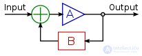
In the case of linear feedback systems, a control loop that includes sensors, control algorithms and actuators is arranged in an attempt to regulate a variable at a setpoint (SP). An everyday example is the cruise control on a road vehicle, where external influences such as hills may cause the speed to change, and the driver has the ability to alter the desired set speed. The PID algorithm in the controller restores the actual speed to the required speed in an optimal way, with minimal delay or overshoot, by regulating the power output of the vehicle's engine.
Control systems that include some sensing of the results they are trying to achieve make use of feedback and can adapt to varying circumstances to some extent. Open-loop control systems do not make use of feedback and operate only in pre-arranged ways.
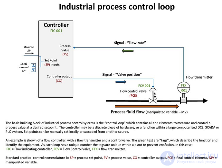
An example of a single industrial control loop, showing continuously modulated control of a process flow.
Logic control systems for industrial and commercial machinery were historically implemented by means of interconnected electrical relays and cam timers using ladder logic. Today, most such systems are built on microcontrollers or on more specialized programmable logic controllers (PLCs). Ladder logic notation is still used as a programming method for PLCs.
Logic controllers can respond to switches and sensors, and can cause machinery to start and stop by means of actuators. Logic controllers are used to sequence mechanical operations in many applications. Examples include elevators, washing machines and other systems with interrelated operations. An automatic sequential control system can trigger a series of mechanical actuators in the correct sequence to perform a task. For example, various electric and pneumatic transducers may fold and glue a cardboard box, fill it with product and then seal it in an automatic packaging machine.
PLC software can be written in various ways – using ladder diagrams, SFCs (sequential function charts) or statement lists.
Two-position control uses a feedback controller that switches abruptly between two states. A simple bimetallic household thermostat can be described as a two-position controller. When the room temperature (PV) falls below the user setting (SP), the heater switches on. Another example is the pressure switch on an air compressor. When the pressure (PV) drops below the setpoint (SP), the compressor switches on. Refrigerators and vacuum pumps contain similar mechanisms. Such simple two-position control systems can be cheap and effective.
Linear control systems use negative feedback to produce a control signal that keeps the regulated PV at the desired SP. There are several types of linear control system with different capabilities.
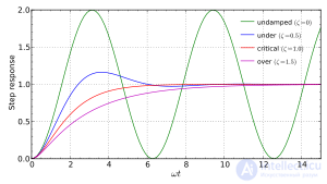
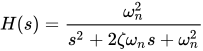 , where
  is the damping ratio and
  is the undamped natural frequency.
Proportional control is a type of linear feedback control system in which a correction is applied to the controlled variable that is proportional to the difference between the desired value (SP) and the measured value (PV). Two classic mechanical examples are the float-operated proportional valve of a toilet and the ball governor.
A proportional control system is more complex than a two-position control system, but simpler than the proportional–integral–derivative (PID) control system used, for instance, in automotive cruise control. Two-position control will work for systems that do not require high accuracy or speed of response, but it is ineffective for fast and timely corrections and responses. Proportional control overcomes this by modulating the manipulated variable (MV), such as a control valve, at a level of gain that avoids instability yet applies the correction as quickly as possible, applying the optimal amount of proportional correction.
A drawback of proportional control is that it cannot eliminate the residual SP – PV error, since an error is required to generate a proportional output. A PI controller can be used to solve this problem. A PI controller uses a proportional term (P) to remove the gross error and an integral term (I) to eliminate the residual offset error by integrating the error over time.
In some systems there are practical limits on the range of the MV. For example, a heater has a limit on how much heat it can produce, and a valve can only open so far. Gain adjustments simultaneously change the range of error values over which the MV lies between these limits. The width of this range, expressed in units of the error variable and hence of the PV, is called the proportional band (PB).
When controlling the temperature of an industrial furnace, it is usually better to control the opening of the fuel valve proportionally to the current needs of the furnace. This helps avoid thermal shocks and transfers heat more efficiently.
At low gain, only a small corrective action is applied when an error is detected. The system may be safe and stable, but it may respond sluggishly when conditions change. Errors will remain uncorrected for relatively long periods of time, and the system will be overdamped. If the proportional gain is increased, such systems become more responsive and errors are eliminated faster. There is an optimal value for the gain setting, at which the whole system is said to be critically damped. Increasing the loop gain beyond this point leads to oscillations in the PV, and such a system is underdamped. Adjusting the gain to achieve critically damped behavior is known as tuning the control system.
In the underdamped case the furnace heats up quickly. Once the setpoint is reached, the heat stored in the heater subsystem and in the furnace walls keeps the measured temperature rising beyond what is required. After the temperature rises above the setpoint, the temperature falls, and eventually heat is supplied again. Any delay in reheating the heater subsystem lets the furnace temperature drop below the setpoint, and the cycle repeats. The temperature oscillations produced by an underdamped furnace control system are undesirable.
In a critically damped system, as the temperature approaches the setpoint the heat input begins to decrease, the furnace heating rate has time to slow down, and the system avoids overshoot. An overdamped system also avoids overshoot, but an overdamped system is needlessly slow to reach the initial setpoint value and to respond to external changes in the system, such as the opening of the furnace door.
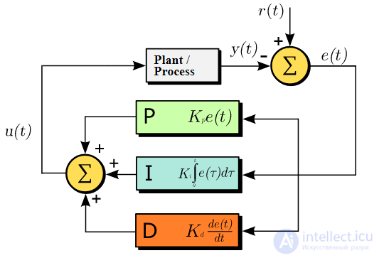 Block diagram of a PID controller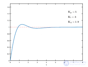
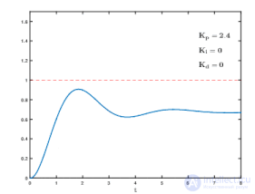
Effect of varying the PID controller parameters (K p, K i, K d ) on the step response of the system.
Purely proportional controllers have to operate with a residual error in the system. Although PI controllers eliminate this error, they may still be slow or generate oscillations. The PID controller removes these last shortcomings by introducing derivative (D) action to preserve stability while improving responsiveness.
The derivative relates to the rate of change of the error over time: if the measured variable is approaching the setpoint rapidly, the actuator is backed off early to let it coast to the required level; conversely, if the measured value starts to deviate rapidly from the setpoint, extra effort is applied – in proportion to that rate – to help bring it back.
In control systems that involve controlling the motion of a heavy object, such as a gun or a camera on a moving vehicle, the derivative action of a well-tuned PID controller can let it reach and hold the setpoint better than most skilled operators could. However, if derivative action is applied excessively, it can cause oscillations.
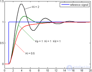
The integral term amplifies the effect of long-term steady-state errors, applying an ever-increasing effort until the error is eliminated. In the furnace example above, operating at various temperatures, if the applied heat does not bring the furnace to the setpoint for any reason, integral action progressively shifts the proportional band relative to the setpoint until the PV error falls to zero and the setpoint is reached.
Some controllers include the ability to limit the "% rise per minute". This option can be very useful for stabilizing small boilers (3 MBTUH), especially in summer, at light loads. "A utility boiler unit may be required to change load at a rate of up to 5% per minute (IEA Coal Online - 2, 2007)".
Filtering the PV or the error signal is possible. This can help reduce instability or oscillations by reducing the system's response to unwanted frequencies. Many systems have a resonant frequency. By filtering out this frequency, stronger overall feedback can be applied before oscillation sets in, making the system more responsive without it hunting.
Feedback systems can be combined. In cascade control, one control loop applies control algorithms to a measured variable relative to a setpoint, but then supplies a varying setpoint to another control loop rather than acting directly on the process variables. If a system has several different measured variables that must be controlled, separate control systems will be used for each of them.
Control engineering in many applications produces control systems that are more complex than PID control. Examples of such application areas are fly-by-wire aircraft flight control systems and chemical plants and oil refineries. Model predictive control systems are developed using specialized computer-aided design software and empirical mathematical models of the controlled system.
Fuzzy logic is an attempt to apply the simple design of logic controllers to the control of complex, continuously varying systems. In principle, a measurement in a fuzzy logic system may be partly true.
The rules of the system are written in natural language and translated into fuzzy logic. For example, the design of a furnace would start with: "If the temperature is too high, reduce the fuel supplied to the furnace. If the temperature is too low, increase the fuel supplied to the furnace."
Measurements taken from the real world (the furnace temperature, for instance) are fuzzified, and the logic is evaluated arithmetically rather than with Boolean logic, while the outputs are de-fuzzified in order to drive the equipment.
When a robust fuzzy scheme is reduced to a single fast calculation, it begins to resemble a conventional feedback solution, and it may appear that the fuzzy design is unnecessary. The fuzzy logic paradigm, however, can provide scalability for large control systems, where traditional methods become unwieldy or expensive to develop.
Fuzzy electronics is an electronic technology that uses fuzzy logic instead of the two-valued logic normally employed in digital electronics.

The control room of a distributed control system (DCS), where plant information and control facilities are displayed on computer graphics screens. The operators are seated, since they can view and control any part of the process from their screens while still retaining an overview of the plant.
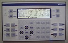
The control panel of a hydraulic heat press with software dedicated to this function
Implementations range from compact controllers, often with software dedicated to a particular machine or device, to distributed control systems for the control of industrial processes.
Logic systems and feedback controllers are usually implemented by means of programmable logic controllers.
1) What do controlling systems do?
2) Indicate the matching for all 5 answer options:
answers a)1; b) 3; c)1; d) 2; e)2;
Automated control system
Hierarchical control system

Comments