
Lecture
Inverter — (Lat. inverto — to turn, to invert) a device for converting direct current into alternating current with a change in voltage magnitude. It is usually a generator of periodic voltage, sinusoidal in shape, or of a discrete signal.
The term inverter (or invertor) can mean:
Voltage inverters can be used as a standalone device or be part of uninterruptible power supplies and systems that supply equipment with alternating-current electrical energy.
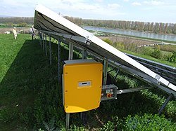
Inverter for mobile solar panels
The operation of a voltage inverter is based on switching a DC voltage source in order to periodically change the polarity of the voltage at the load terminals. The switching frequency is set by control signals generated by the control circuit (controller). The controller can also handle additional tasks:
By operating principle, inverters are divided into:
 pulsates at twice the frequency. The primary power supply must allow operation with pulsating and even sign-changing consumption currents. The variable components of the primary current determine the level of interference at the terminals of the power supply.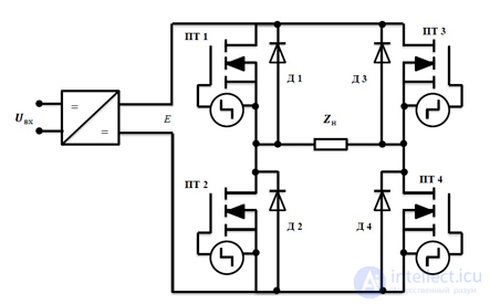
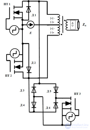
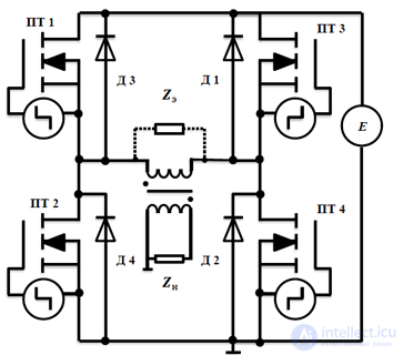
There are a large number of variants for building inverter circuits. Historically, the first were mechanical inverters, which, in the era of development of semiconductor technologies, were replaced by more advanced inverters based on semiconductor elements, and digital voltage inverters. Nevertheless, as a rule, three basic voltage inverter circuits are distinguished:
Field of application: uninterruptible power supply devices with a power of more than 500 VA, installations with a high voltage value (220..360 V).
Field of application: Uninterruptible power supply devices for computers with a power of (250..500 VA), at a low voltage value (12..24 V), voltage converters for mobile radio communication systems.
Field of application: Uninterruptible power supply devices for critical consumers with a wide range of power ratings: from units to tens of kVA .
The conversion of the DC voltage of the primary source into AC voltage is achieved by means of a group of switches, periodically commutated in such a way as to obtain an alternating-sign voltage at the load terminals and to ensure a controlled mode of circulation in the reactive energy circuit. In such modes, proportionality of the output voltage is guaranteed. Depending on the design of the switching module (the inverter's power switch module) and the algorithm for generating control actions, such a factor may be the relative duration of the switch control pulses or the phase shift of the control signals of the antiphase switch groups. In the case of uncontrolled modes of reactive energy circulation, the response of a consumer with reactive load components affects the shape of the voltage and its output magnitude .
The design principle of such an inverter is that, by means of preliminary high-frequency conversion, unipolar stepped voltage curves are formed, approaching in shape a unipolar sinusoidal curve with a period equal to half the period of variation of the inverter's output voltage. Then, usually by means of a bridge inverter, the unipolar stepped voltage curves are converted into a bipolar curve of the inverter's output voltage.
The design principle of such an inverter is that, by means of preliminary high-frequency conversion, a DC voltage is obtained whose value is close to the amplitude value of the inverter's sinusoidal output voltage. This DC voltage is then, usually by means of a bridge inverter, converted into an AC voltage whose shape is close to sinusoidal, owing to the application of appropriate principles for controlling the transistors of this bridge inverter (the principles of so-called «multiple pulse-width modulation»). The idea of this «multiple» PWM is that, over the interval of each half-cycle of the inverter's output voltage, the corresponding pair of transistors of the bridge inverter is switched at high frequency (multiple times) under pulse-width control. Moreover, the duration of these high-frequency switching pulses varies according to a sinusoidal law . Then, by means of a high-frequency low-pass filter, the sinusoidal component of the inverter's output voltage is extracted. .
When using a unipolar DC voltage source (levels 0 and Ud are available, where Ud is the DC voltage powering the inverter), the effective value of the first harmonic of the phase voltage
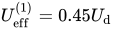
When using a bipolar DC voltage source (levels 0, -Ud/2 and Ud/2 are available), the amplitude value of the first harmonic of the phase voltage
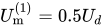
respectively, the effective value
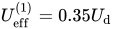
Self-excited inverters (self-oscillators) are among the simplest devices for converting DC energy. The relative simplicity of the technical solutions, combined with a fairly high energy efficiency, has led to their widespread use in low-power power supplies in industrial automation systems and in generating rectangular-shaped signals, especially in those applications where there is no need to control the energy transfer process. Positive feedback is used in these inverters, ensuring their operation in a stable self-oscillation mode, and the switching of the transistors is accomplished by saturation of the transformer core material. [10] Due to the method of switching the transistors, by means of saturation of the transformer core material, a drawback of these inverter circuits is noted, namely low efficiency, which is explained by large losses in the transistors. Therefore, such inverters are used at frequencies  of no more than 10 kHz and an output power of up to 10 W. Under significant overloads and short circuits in the load, in any of the self-excited inverters, a breakdown of self-oscillations occurs (all transistors switch to the closed state).
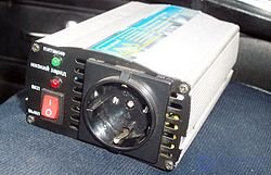
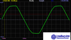
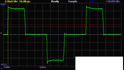
There are several groups of inverters:
For the overwhelming majority of household appliances it is not acceptable to use an AC voltage with a simplified signal shape. A sine wave is important for devices containing electric motors/transformers, as well as some telecommunications, measuring, and laboratory instruments, medical equipment, and professional audio equipment. The choice of inverter is made based on the peak power consumption of the standard 220V/50Hz voltage.
There are three operating modes of an inverter:
For several seconds most inverter models can deliver 1.5-2 times the rated power. A strong short-term overload occurs, for example, when a refrigerator switches on.
A 150 W inverter is enough to power practically any laptop from a car's onboard electrical system. 7.5 W is enough to power and charge mobile phones, audio devices and cameras.
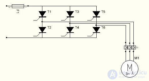
Three-phase inverters are usually used to create three-phase current for electric motors, for example, to power a three-phase induction motor. In this case the motor windings are connected directly to the inverter output.
High-power three-phase inverters are used in traction converters in the electric drives of locomotives, ships, trolleybuses (for example, the AKSM-321), trams, rolling mills, drilling rigs, and in inductors (induction heating installations[12]).
The figure shows the circuit of a thyristor traction converter based on the «Larionov star» scheme. Theoretically another variant of the Larionov circuit, the «Larionov delta», is also possible, but it has different characteristics (equivalent internal active resistance, copper losses, etc.).
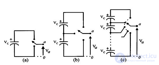
Multilevel inverters include a matrix of power semiconductors and capacitor voltage sources, the output of which generates voltages with stepped signal shapes. Switching of the switches makes it possible to add capacitor voltages that reach a high output voltage, while the power semiconductors only have to withstand reduced voltages. The figure on the right shows the schematic diagram of one phase leg of inverters with different numbers of levels, for which the semiconductor power rating is represented by an ideal switch with several positions.
A two-level inverter generates an output voltage with two values (levels) relative to the negative terminal of the capacitor [Fig. (a)], while a three-level inverter generates three voltages, and so on.
Let us assume that m is the number of steps of the phase voltage relative to the negative terminal of the inverter, then the number of steps in the voltage between two phases of the load k,

and the number of steps p in the phase voltage of a three-phase load in a connection

There are three different topologies for multilevel inverters: diode-clamped (neutral-point clamped); capacitor-clamped (flying capacitors); and cascaded multicell with separate DC sources. In addition, several modulation methods and control strategies have been developed or adopted for multilevel inverters, including the following: multilevel sinusoidal pulse-width modulation (PWM), multilevel selective harmonic elimination, and space vector modulation (SVM).
The main advantages of multilevel inverters are as follows:
1) They can generate output voltages with extremely low distortion and reduce dv/dt.
2) They draw input current with very low distortion.
3) They generate a lower common-mode (CM) voltage, thereby reducing stress on motor bearings. In addition, with the help of complex modulation methods, CM voltages can be eliminated.
4) They can operate at a lower switching frequency.
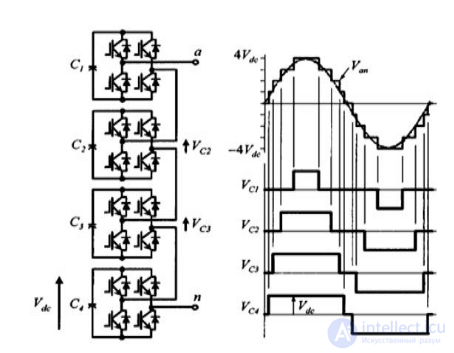
Various converter topologies presented here are based on the series connection of single-phase inverters with separate DC sources. The figure on the right shows the power circuit for one phase section of a nine-level inverter with four cells in each phase. The resulting phase voltage is synthesized by adding the voltages generated by the various sections.
Each single-phase full-bridge inverter generates three voltages at its output: + Vdc, 0, and - Vdc. This is made possible by connecting capacitors in series with the ac side through four power switches. The resulting AC output voltage waveform ranges from -4 Vdc to 4 Vdc with nine levels and a stepped waveform, almost sinusoidal, even without the use of filters.

Comments