
Lecture
LED drivers are used to provide power to LEDs, in particular ultra-bright LEDs; they are a stabilized current source that converts mains voltage into direct current.
Drivers provide a stable current to the load, whereas power supplies provide a constant output voltage. Since the brightness of an LED's glow depends on the strength of the current flowing through it, not on the voltage, it is important to provide a stable current in order to ensure the most uniform glow possible.
Advantages of an LED driver over power supplies:
Drivers can be made using transistors or PWM controllers; most models are implemented using PWM, since this solution provides higher current-stabilization accuracy and the circuit is designed for larger loads. The only advantage of drivers implemented on transistors is their low price.
LED drivers are manufactured for a specific voltage:
The most common LED driver models are rated for a current of 300 and 700 mA. If necessary, you can easily buy LED drivers that output currents of several amperes.
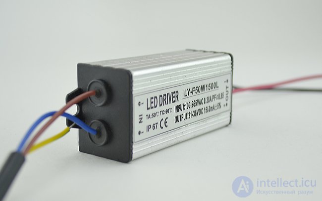
Each driver is matched with a strictly corresponding number of LEDs of a certain power, which is why they are most often used in products manufactured industrially, rather than in individual solutions.
But universal drivers are also produced, which allow for the use of a variable number of LEDs, provided that their total power does not exceed the rated power of the driver; the efficiency of such drivers is lower, and the price is somewhat higher.
Also an important advantage of LED drivers is their very compact size, thanks to which they can be placed in almost any housing and inconspicuously positioned in interior niches.
LED drivers are classified by device type into linear and switching types. The structure and typical circuit of a linear-type LED driver is a current generator on a p-channel transistor. Such devices provide smooth current stabilization under conditions of unstable voltage on the input channel. They are simple and cheap devices, but are characterized by low efficiency, generate a lot of heat during operation, and cannot be used as drivers for high-power LEDs.
Switching devices create a series of high-frequency pulses in the output channel. Their operation is based on the principle of PWM (pulse-width modulation), where the average value of the output current is determined by the duty cycle, i.e. the ratio of the pulse duration to the number of its repetitions. The change in the value of the average output current occurs because the pulse frequency remains unchanged while the duty cycle changes from 10-80%.
Thanks to their high conversion efficiency (up to 95%) and compactness, these devices have found wide application for portable LED constructions. In addition, the efficiency of the devices has a positive effect on the operating life of autonomous power devices. Switching-type converters are compact in size and are distinguished by a broad range of input voltages. The disadvantage of these devices is a high level of electromagnetic interference.
Modern LED drivers are compatible with devices for adjusting the brightness of semiconductor devices. The use of dimmable drivers makes it possible to control the level of illumination in rooms: reducing the intensity of light during the daytime, highlighting or hiding certain elements in the interior, zoning the space. This, in turn, makes it possible not only to use electricity rationally, but also to save the service life of the LED light source.
Dimmable drivers come in two types. Some are connected between the power supply and the LED sources. Such devices control the energy coming from the power supply to the LEDs. These devices are based on PWM control, in which energy reaches the load in the form of pulses. The pulse duration determines the amount of energy from the minimum to the maximum value. Drivers of this type are used mostly for LED modules with a fixed voltage, such as LED strips, running text displays, and so on.
Dimmable converters of the second type directly control the power supply itself. Their operating principle consists both of PWM regulation and of controlling the magnitude of the current flowing through the LEDs. Dimmable drivers of this type are used for LED devices with stabilized current. It should be noted that when controlling LEDs by means of PWM regulation, effects that negatively affect vision are observed.
Comparing these two regulation methods, it should be noted that when regulating the current through LED sources, not only does the brightness of the glow change, but so does the color of the glow. Thus, white LEDs emit a yellowish light at lower current, and glow blue as the current increases. When controlling LEDs by means of PWM regulation, effects that negatively affect vision are observed, along with a high level of electromagnetic interference. For this reason, PWM control is used quite rarely, unlike current regulation.
Many manufacturers produce driver chips for LEDs, allowing the sources to be powered from a reduced voltage. All existing drivers are divided into simple ones, built on the basis of 1-3 transistors, and more complex ones using special chips with pulse-width modulation.
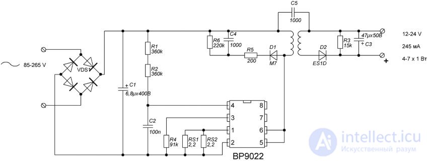
LED driver circuit for 1W
ON Semiconductor offers a wide selection of chips as the basis for drivers. They are distinguished by an acceptable cost, excellent conversion efficiency, economy, and a low level of electromagnetic pulses. The manufacturer offers the UC3845 pulse-type driver with an output current of up to 1A. This chip can be used to implement a driver circuit for a 10W LED.
The HV9910 (Supertex) electronic component is a popular driver chip, thanks to its simple circuit design and low price. It has a built-in voltage regulator and pins for brightness control, as well as a pin for programming the switching frequency. The output current value is up to 0.01A. This chip can be used to implement a simple LED driver.
Based on the UCC28810 chip (manufactured by Texas Instruments), a driver circuit for high-power LEDs can be created. In such an LED driver circuit, an output voltage of 70-85V can be generated for LED modules consisting of 28 LED sources with a current of 3 A.
Useful tip! If you plan to buy ultra-bright 10 W LEDs, a pulse driver based on the UCC28810 chip can be used for structures made of them.
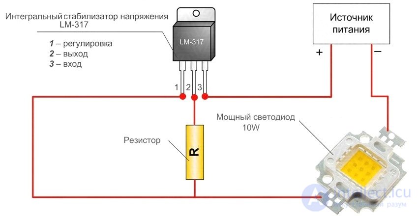
High-power LED connection diagram
Clare offers the creation of a simple pulse-type driver based on the CPC 9909 chip. It includes a converter controller housed in a compact package. Thanks to the built-in voltage regulator, the converter can be powered from a voltage of 8-550V. The CPC 9909 chip allows the driver to operate under a wide range of temperature conditions from -50 to 80°C.
To determine the output voltage of an LED driver, it is necessary to calculate the ratio of power (W) to the current value (A). For example, a driver has the following characteristics: power 3 W and current 0.3 A. The calculated ratio is 10V. Thus, this will be the maximum output voltage value of this converter.
If it is necessary to connect 3 LED sources, the current of each of which is 0.3 mA at a supply voltage of 3V. Connecting one of the devices to the LED driver, the output voltage will be equal to 3V and the current 0.3 A. Assembling two LED sources in series, the output voltage will be equal to 6V and the current 0.3 A. Adding a third LED to the series chain, we get 9V and 0.3 A. With parallel connection, 0.3 A will be distributed equally between the LEDs at 0.1 A each. Connecting LEDs to a device rated at 0.3 A at a current value of 0.7, they will get only 0.3 A.
This is the algorithm of operation of LED drivers. They output the amount of current they are designed for. The method of connecting LED devices does not matter in this case. There are driver models that allow for any number of LEDs to be connected to them. But then there is a limitation on the power of the LED sources: it must not exceed the power of the driver itself. Drivers are produced that are designed for a specific number of connected LEDs. It is permissible to connect a smaller number of LEDs to them. But such drivers have low efficiency, unlike devices designed for a specific number of LED devices.
It should be noted that drivers designed for a fixed number of emitting diodes have protection against emergency situations. Such converters operate incorrectly if a smaller number of LEDs are connected to them: they will flicker or not light up at all. Thus, if voltage is applied to the driver without a corresponding load, it will operate unstably.
Driver circuits for powering LED devices with a dissipation power of 3 W can be made in two versions. The first assumes a power supply with a voltage from 6 to 30V. In the other circuit, power is supplied from an AC source with a voltage from 12 to 18V. In this case, a diode bridge is introduced into the circuit, at the output of which a capacitor is installed. It helps to smooth out voltage fluctuations, its capacitance is 1000 μF.
For the first and second circuits, the capacitor (CIN) is of particular importance: this component is designed to reduce ripple and compensate for the energy accumulated by the inductor when the MOSFET transistor turns off. In the absence of a capacitor, all the inductor's energy would pass through the Schottky diode (D) to the supply voltage pin (VIN) and cause breakdown of the chip relative to the supply.
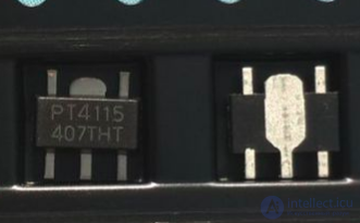
PT4115 chip
Useful tip! It is essential to keep in mind that connecting the LED driver without an input capacitor is not permitted.
Taking into account the number of LEDs and how much they consume, the inductance (L) is calculated. In the LED driver circuit, an inductance value of 68-220 µH should be chosen. This is indicated by the technical documentation data. A small increase in the value of L can be allowed, but it should be taken into account that this will then reduce the efficiency of the circuit as a whole.
As soon as voltage is applied, the current value as it passes through resistor RS (which acts as a current sensor) and L will be zero. Next, the CS comparator analyzes the potential levels before and after the resistor – as a result, a high concentration appears at the output. The current going to the load rises to a certain value, controlled by RS. The current increases depending on the value of the inductance and on the magnitude of the voltage.
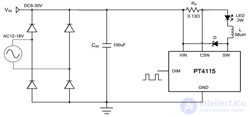
LED driver circuit using the PT4115
The components surrounding the PT4115 chip are selected in accordance with the manufacturer's instructions. For CIN, a low-impedance capacitor (a capacitor with low ESR) should be used, since the use of other equivalents will negatively affect the driver's efficiency. If the device will be powered from a unit with stabilized current, one capacitor with a capacitance of 4.7 µF or more will be needed at the input. It is recommended to place it near the chip. If the current is variable, a solid-state tantalum capacitor with a capacitance of no less than 100 µF will need to be introduced.
In the connection circuit for 3 W LEDs, an inductor of 68 µH must be installed. It should be located as close as possible to the SW pin. The inductor can be made by hand. To do this, you will need a ring from a failed computer and winding wire (PEL-0.35). A FR103 diode can be used as diode D. Its parameters: capacitance 15 pF, recovery time 150 ns, temperature from -65 to 150°C. It can handle current pulses of up to 30 A.
The minimum value of resistor RS in the LED driver circuit is 0.082 Ohm, current – 1.2 A. To calculate the resistor, you need to use the current value required for the LED. Below is the formula for the calculation:
RS = 0.1 / I,
where I – the rated current value of the LED source.
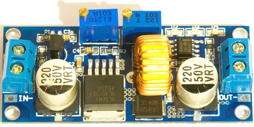
Low-voltage driver on a chip
The value of RS in the LED driver circuit is 0.13 Ohm, and correspondingly the current value – 780 mA. If such a resistor cannot be found, several low-resistance components can be used, applying the resistance formula for parallel and series connection when calculating.

Comments