
Lecture
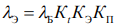
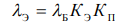
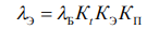
The values of the operational failure rate λE of most groups of elements (components) are calculated using the mathematical model

where λB – base failure rate of elements of a given group;
Ki – coefficients that account for changes in the operational failure rate depending on various factors;
m – number of factors taken into account.
For individual groups of complex electronic components (ERI), the total failure flow of which is made up of independent failure flows of the constituent parts of the ERI (for example, the electromagnetic coil and contact system of a relay), the mathematical model for calculating the operational failure rate has the form

where λB j – initial (base) failure rate of the j-th part of the product, j = 1, …, n; n – number of constituent parts of the product;
Ki(j) – coefficient accounting for the influence of the i-th factor for the j-th part of the product; i = 1, …, m; j =1, …, n;
mj – number of factors taken into account for the i-th part of the product.
Formula (5.2) takes into account that different parts (components) of the ERI may have different values of the coefficients accounting for the influence of one and the same factor, in particular the quality level of manufacture under production conditions (type of acceptance). For example, the electromagnetic coil of a relay may be manufactured to a quality level determined by acceptance “1” at one plant, while the contact system and the assembly of the relay as a whole may be produced to acceptance “3” at another plant. The specific formulation of the models for elements also depends on the design features of the element and the number of parts involved (for example, contacts in the case of switching products or connectors). The individual (per-component) constituents of the failure rate λB , called base failure rates, may be taken from reference handbooks or calculated using the models given in the corresponding sections of this textbook.
Table 5.1 presents the mathematical models recommended for calculating (predicting) the values of λE for typical elements of REE produced in CIS countries. In systematizing these models, reliability reference handbooks developed in Russia [11, 12] were used as the basis. Refinement of the models was performed based on analysis and systematization of the military reference guides and standards of the USA, France and China [13–15]. An explanation of the quantities appearing in the mathematical models is given in Table 5.2.
Table 5.1 Mathematical models for determining the values of λE for elements produced in CIS countries
|
Class (group) of elements |
Form of the mathematical model |
Numbers of the formulas and tables for determining the coefficients1 |
|
Integrated circuits (typical electrical operating mode) |
|
(5.3), (5.4), Tables 5.4–5.6 |
|
Integrated circuits operating in derated electrical modes |

|
(5.5), (5.3), Tables 5.4–5.6 |
|
Diodes, except zener diodes. Diode assemblies |
|
(5.7), Tables 5.7–5.10 |
|
Zener diodes |
|
(5.7), Table 5.7 |
Continuation of Table 5.1
|
|
Class (group) of elements |
Form of the mathematical model |
Numbers of the formulas and tables for determining the coefficients1 |
|||
|
|
Bipolar transistors, transistor assemblies |
|
(5.7), Tables 5.7–5.10 |
|||
|
|
Field-effect transistors |
|
(5.7), Tables 5.7, 5.8 |
|||
|
|
Thyristors |
|
(5.7), Tables 5.7, 5.9 |
|||
|
|
Microwave diodes |
|
– |
|||
|
|
Bipolar high-power microwave transistors |
|
– |
|||
|
|
Optoelectronic elements (LEDs, optocouplers) |
|
(5.8)–(5.10) |
|||
|
|
Optoelectronic integrated circuits (typical electrical operating mode) |
|
– |
|||
|
|
Non-polar capacitors, oxide-electrolytic, except pulse type |
|
(5.11), Tables 5.11, 5.12 |
|||
|
|
Oxide-electrolytic pulse type |
|
– |
|||
|
|
Fixed resistors: metal-film
metallized, composition |
|
(5.12), Tables 5.13–5.15 (KΔ – see p. 30) |
|||
|
|
Variable resistors: wire-wound |
|
(5.12), Table 5.13, 5.15 |
|||
|
|
non-wire-wound |
|
(5.12), Table 5.13, 5.15, 5.16 |
|||
|
|
Thermistors |
|
– |
|||
|
|
Switching elements (switches, toggle switches, push-buttons, etc.) |
|
(5.13)–(5.14), Table 5.17 |
|||
|
|
Connectors: low-frequency |
|
(5.15)–(5.17) |
|||
|
|
radio-frequency |
|
(5.15)–(5.19) |
|||
|
|
Indicators |
|||||
|
|
semiconductor |
|
(5.8) |
|||
|
|
vacuum fluorescent |
|
(5.20) |
|||
|
|
other indicators, CRTs, picture tubes, etc. |
|
– |
|||
|
|
Transformers |
|
(5.21)–(5.24), Table 5.18 |
|||
|
|
Chokes, inductors |
|
(5.25) |
|||
|
|
General-purpose electromagnetic relays |
|
(5.25)–(5.28), Table 5.19 |
|||
|
|
Relays and protective circuit breakers |
|
(5.25), (5.27), |
|||
|
|
|
Table 5.19 |
|
|||
End of Table 5.1
|
Class (group) of elements |
Form of the mathematical model |
Numbers of the formulas and tables for determining the coefficients1 |
|
Other elements and components |
|
|
|
Piezoelectric resonators |
|
(5.29) |
|
Fuses |
|
(5.30) |
|
Boards with plated through-holes (through-hole soldered joints) |
|
(5.30) |
|
Connections, including soldered joints 2 |
|
(5.30) |
|
Electric light bulbs |
|
– |
|
Cables, cords, wiring conductors |
|
(5.31)–(5.34), Table 5.20 |
Notes: 1 The values of the coefficients KE and KP are given in Tables 5.22 and 5.23.
2
The model applies to any connections (soldered joints) used in all boards (assemblies), except connections (soldered joints) in boards with plated through-holes. All types of soldering of plated through-holes should be accounted for in the model for calculating the operational failure rate of boards with plated through-holes.
Table 5.2 Explanations of the quantities (parameters) appearing in the mathematical models
|
|
Parameter |
Explanation |
||
|
|
Components appearing in the models for all types of elements |
|||
|
|
λB |
Base failure rate of the elements of a given group (or a specific type), corresponding to an ambient temperature of +25 °C and rated electrical load, i.e. an electrical load factor value of KN = 1 |
||
|
|
KR |
Mode factor, dependent on the electrical load (the factor KN) and the case temperature of the element |
||
|
|
Kt |
Coefficient dependent on the case temperature of the element (component) |
||
|
|
KE |
Operating-environment factor, dependent on the severity of the operating conditions of the REU |
||
|
|
KP |
Acceptance factor, accounting for the stringency of the quality-control requirements and the acceptance rules for elements (REU components) under production conditions |
||
|
|
Components appearing in the models for integrated circuits (ICs) |
|||
|
|
KIS |
Coefficient accounting for the number of elements in the IC or bits (for memory ICs) |
||
|
|
Kcorp |
Coefficient accounting for the package type |
||
|
|
KV |
Coefficient accounting for the supply voltage for CMOS ICs |
||
|
|
Components appearing in the models for semiconductor devices |
|||
|
|
KF |
Coefficient accounting for the functional operating mode of the device |
||
|
|
KD |
Coefficient dependent on the value of the maximum permissible power (or current) load per the technical specification |
||
|
KU |
Coefficient dependent on the ratio of the operating voltage to the maximum permissible voltage per the technical specification (voltage load factor) |
|
||
End of Table 5.2
|
|
Parameter |
Explanation |
||
|
|
Components appearing in the models for capacitors |
|||
|
|
KC |
Coefficient dependent on the value of the rated capacitance |
||
|
|
Components appearing in the models for resistors |
|||
|
|
KR |
Coefficient dependent on the value of the rated resistance |
||
|
|
KM |
Coefficient dependent on the value of the rated power (for metal-film resistors) |
||
|
|
Kdop |
Coefficient dependent on the value of the resistance tolerance (for metal-film resistors) |
||
|
|
KU |
Coefficient dependent on the ratio of the operating voltage Uop on the resistor to the maximum permissible voltage per the technical specification (UTS); |
||
|
|
Components appearing in the models for switching products and connectors |
|||
|
|
KK |
Coefficient dependent on the number of contacts involved |
||
|
|
Kn |
Coefficient dependent on the number of mating-unmating cycles n (connectors) |
||
|
|
tp |
Contact overheating temperature per the technical specification at maximum current load. Used to select the coefficient KK |
||
|
|
KF |
Coefficient accounting for the number of switching operations per hour |
||
|
|
λB(k.i) |
Base failure rate of the switching product as a whole, 1/h |
||
|
|
λB(on) |
Additional failure rate per actuation when the switching product operates as part of an REU, 1/actuation |
||
|
|
L |
Superscript indicating that the corresponding quantities relate to the electromagnetic coil of the relay |
||
|
|
λB(com) |
Relay failure rate per switching operation |
||
|
|
F |
Average switching frequency of the product per hour in the REU |
||
|
|
N |
Number of active contacts (contact points) |
||
|
|
Components appearing in the models for printed circuit boards with plated through-holes |
|||
|
|
B |
Base failure rate of interconnections depending on the technology |
||
|
|
Ksl |
Coefficient accounting for the number of layers n in the board |
||
|
|
N1 |
Number of through-holes soldered by the “wave soldering” method |
||
|
|
N2 |
Number of through-holes soldered by the manual method |
||
|
|
Components appearing in the models for cords, cables, wiring conductors |
|||
|
|
L |
Length of the cable product in the REU, m |
||
|
|
KT |
Coefficient dependent on the operating temperature, material, and design of the insulation and sheath |
||
|
|
λB |
Base failure rate of cable products at a temperature of +25 ºC, 1/h · m (Table 5.3) |
||
|
|
Components appearing in the models for connections |
|||
|
λB |
Base failure rate of the connection (Table 5.3) |
|
||
The acceptance factor KP corrects the reference data on failure-free reliability to account for the manufacturing quality level of the elements (components) used. The correction is performed relative to the level for which the reference data on the element's failure rate are given. As this quality level, the reference handbooks developed by the Ministry of Defence of the former USSR, and later of Russia, adopted acceptance “5” – general military application (GMA, MA) [16].
Table 5.3 gives the base failure rates (λB ) of groups of elements (components) of REE, corresponding to acceptance “5” (GMA acceptance), for which the acceptance factor KP = 1.0. Recalculation of the λB values for other types of acceptance is performed using the values of KP given in Section 5.13.
Table 5.3
Base failure rates of groups of elements and components of REE
|
Group of elements |
λB , 10– 6 1/h |
|
1. Integrated circuits (ICs) |
|
|
Semiconductor digital: logic, arithmetic, microprocessors and microprocessor sets, shift registers and other random-access memory (RAM) read-only memory (ROM, PROM, EPROM) |
0.023 0.030 0.018 |
|
Semiconductor analog |
0.028 |
|
Hybrid ICs |
0.043 |
|
2. Semiconductor devices (SD) |
|
|
Rectifier diodes |
0.091 |
|
Rectifier stacks (bridges) |
0.21 |
|
Pulse diodes |
0.025 |
|
Trimmer varicaps |
0.022 |
|
Zener diodes |
0.0041 |
|
Bipolar silicon transistors, except microwave |
0.044 |
|
Field-effect transistors: silicon gallium arsenide |
0.065 0.578 |
|
Silicon thyristors |
0.2 |
|
Microwave diodes: silicon (except multiplier and tuning types) silicon multiplier and tuning gallium arsenide |
0.162 1.61 0.21 |
|
Low- and medium-power microwave transistors |
0.064 |
|
High-power microwave transistors |
0.18 |
|
3. Optoelectronic semiconductor devices |
|
|
Silicon-based photodiodes |
0.185 |
|
Phototransistors |
0.15 |
|
Photoresistors based on PbS |
1.8 |
|
Infrared and visible-range emitting diodes (LEDs) |
0.034 |
|
Diode and transistor optocouplers |
0.051 |
|
Thyristor and resistor optocouplers, optoelectronic ICs |
0.19 |
Continuation of Table 5.3
|
|
Element group |
λB , 10–6 1/h |
||
|
|
4. Character-forming (alphanumeric) indicators |
|
||
|
|
Semiconductor indicators 1: alphanumeric displays with a diode matrix |
0.42 0.21 |
||
|
|
Vacuum fluorescent indicators: numeric alphanumeric Vacuum incandescent numeric indicators Gas-discharge indicators: numeric alphanumeric Liquid-crystal multi-digit numeric indicators |
0.83 0.69 0.31
0.79 2.25 0.88 |
||
|
|
5. Capacitors |
|
||
|
|
mica ceramic paper and metallized-paper with organic synthetic dielectric aluminum electrolytic |
0.04 0.022 0.019 0.028 0.173 |
||
|
|
6. Resistors |
|
||
|
|
Fixed non-wirewound resistors: metal-dielectric, metallized composition Variable resistors: non-wirewound wirewound Thermistors |
0.044 0.034
0.179 0.183 0.007 |
||
|
|
7. Switching elements 2 |
|
||
|
|
Rotary (wafer) switches Toggle switches Pushbuttons, pushbutton switches Microswitches Reed-based switches Magnetically operated contacts: normally-open type changeover type |
0.058 / 0.0027 (1/on) 0.1 / 0.0064 (1/on) 0.16 / 0.009 (1/on) 0.045/0.0019 (1/on) 0.13 / 0.005 (1/on)
0.0007 (1/actuation) 0.018 (1/actuation) |
||
|
|
8. Connectors: |
|
||
|
|
low-frequency rectangular for printed-circuit mounting low-frequency for chassis mounting radio-frequency with polyethylene insulation |
0.0041 0.0104 0.015 |
||
|
|
10. Other elements and components |
|
||
|
|
Transformers: power converters matching, pulse, etc. |
0.0035 0.0072 0.0019 |
||
|
|
Cathode-ray tubes: oscilloscope, indicator monochrome picture tubes color picture tubes |
1.67 1.1 13.17 |
||
|
|
Chokes |
0.033 |
||
|
Inductors |
0.01 |
|
||
|
General-purpose electromagnetic relays 3 |
0.0304 (1/cyc.) |
|
||
End of table 5.3
|
Element group |
λB , 10–6 1/h |
|
Piezoelectric devices (crystal resonators, sensors, filters) |
0.026 |
|
Delay lines |
0.04 |
|
Fuses |
0.011 |
|
Fuse holders |
0.003 |
|
Indicator lamps at the minimum burning duration Tmin specified in the technical specification: at AC voltage up to 12 V at DC voltage up to 12 V at AC voltage 200…240 V |
1.8 5.4 77.8 |
|
Connections (base failure rate values): hand soldering without wire-wrap hand soldering with wire-wrap wave soldering crimping (crimp termination) terminal block (assembly) |
0.0013 0.00007 0.000069 0.00012 0.062 |
|
Solder joints of plated-through holes in boards with metallized holes (base failure rate values depending on the interconnection technology): printed-circuit assembly discrete-wire assembly |
0.000017 0.00011 |
|
Cables, cords, wiring conductors (base failure rate values) 4: radio-frequency coaxial cables (conductors) low-voltage wiring conductors of ordinary heat resistance flexible rubber-insulated power cords (without power plugs) |
0.00127 (1/m) 0.0577 (1/m) 0.037 (1/m) |
Notes: 1. For ICs, the base failure rates correspond to ICs of medium integration scale not in plastic packages, under conditions of typical (averaged) electrical loading and an ambient temperature t = +25 º C.
2. For discrete semiconductor devices (DSD), including semiconductor indicators, the failure rate corresponds to devices not in plastic (polymer) packages.
1
The value given is per one digit (segment) of the indicator (diode matrix).
Subsections 5.2–5.13 present formulas (models) and tables obtained by analyzing reference books [10–12], which can be used to determine the coefficients included in the models for calculating λE values.
To determine the coefficient KIS, which accounts for the number of elements in the IC or bits (for memory ICs), the mathematical model obtained from the tabular data of work [15] can be used:
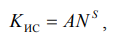 (5.3)
where A, S – constant coefficients of the model (table 5.4); N – number of elements in the IC or bits.
Table 5.4 Coefficients of models (5.3) and (5.4) for various IC groups
|
IC group |
A |
S |
B |
|
1. Semiconductor digital (logic, arithmetic, microprocessors, shift registers, etc.) |
0.336 |
0.288 |
0.021 |
|
2. Random-access memory devices (RAM) |
0.468 |
0.168 |
0.021 |
|
3. Read-only memory devices (ROM) and programmable ROM (PROM) |
0.963 |
0.128 |
0.021 |
|
4. Reprogrammable ROM (EPROM) |
1.113 |
0.128 |
0.021 |
|
5. Analog ICs |
0.478 |
0.253 |
0.023 |
|
6. Hybrid ICs |
0.796 |
0.120 |
0.024 |
Values of the coefficient Kt can be obtained from the expression
 (5.4)
where B – a constant depending on the functional purpose of the IC
(see table 5.4); tokr – temperature of the environment surrounding the IC, ºC.
For ICs whose operation is permitted under derated electrical conditions, the values of the coefficient KP can be calculated using the mathematical model:
 , (5.5)
where Kobl – the ratio of the operating electrical load to the maximum permissible one (the electrical characteristic taken into account is selected depending on the nature of the derating of the IC's electrical mode).
The value of tokr can be determined from the expression
 (5.6)
where trab max – the upper value of the operating temperature of the REE;
tZ – overheating in the heated zone of the REE assembly (usually tZ ≤ 25…30 ºC).
Values of the coefficient Kcorp depending on the IC package type are given in table 5.5. Values of the coefficient KV should be selected from table 5.6.
Table 5.5 Values of the coefficient Kcorp
|
Package |
Kcorp |
Package |
Kcorp |
|
All packages except plastic (polymer) |
1.0 |
Plastic (polymer) |
3.0 |
Table 5.6 Values of the coefficient KV depending on maximum supply voltage values
|
Technology |
Value of KV for supply voltage, V |
||
|
up to 10 |
> 10 to 12.6 |
> 12.6 to 15 |
|
|
CMOS |
1.0 |
3.0 |
10.0 |
|
Other technology types |
1.0 |
||
Values of the coefficient KP can be calculated using the mathematical model:

where A, NT, TM, L, t – model constants; tokr – ambient temperature;
KN – electrical load factor (see table 3.1).
Values of the constants included in model (5.7) are given in table 5.7.
Table 5.7 Constants of model (5.7)
|
Element group |
A |
NT |
TM |
L |
t |
|
Diodes, except zener diodes. Diode assemblies |
44.1025 |
–2138 |
448 |
17.7 |
150 |
|
Zener diodes |
2.1935 |
–800 |
448 |
14.0 |
150 |
|
Bipolar transistors, except high-power microwave. Transistor assemblies. Field-effect transistors |
5.2 |
–1162 |
448 |
13.8 |
150 |
|
Thyristors |
37.2727 |
–2050 |
448 |
9.6 |
150 |
Values of the coefficient KF should be selected from table 5.8.
Table 5.8
Effect of functional operating mode on the coefficient KF
|
Device group |
Functional operating mode |
KF |
|
Rectifier, general-purpose, pulse diodes, rectifier stacks, trimmer varicaps, diode assemblies |
Linear Switching Rectifying |
1.0 0.6 1.5 |
|
Bipolar transistors, except high-power microwave. Transistor assemblies |
Linear Switching Oscillator High-voltage devices |
1.5 0.7 0.7 1.5 |
|
Field-effect transistors |
Silicon devices: linear switching oscillator microwave-band Gallium arsenide devices |
1.5 0.7 1.0 5.0 7.5 |
When selecting the coefficient KD, follow table 5.9.
Table 5.9 Values of the coefficient KD
|
Device group |
Load |
Load value |
KD |
|
Diodes, diode assemblies |
Maximum permissible mean forward current per technical specification Ipr.sr max TU, A |
≤ 1 > 1 ≤ 3 > 3 ≤ 10 > 10 ≤ 20 |
0.6 0.8 1.0 2.0 |
|
Bipolar transistors, except high-power microwave. Transistor assemblies. Trimmer varicaps |
Maximum permissible dissipated power per technical specification Pmax TU, W |
≤ 1 > 1 ≤ 5 > 5 ≤ 20 > 20 ≤ 50 > 50 ≤ 200 |
0.5 0.8 1.0 1.3 2.5 |
|
Thyristors |
Maximum permissible mean forward current per technical specification Ipr.sr max TU, A |
≤ 1 > 1 ≤ 5 > 5 ≤ 25 > 25 ≤ 50 |
1.0 3.0 6.0 10.0 |
Values of the coefficient KU are given in table 5.10.
Table 5.10 Values of the coefficient KU
|
Device group |
Voltage load factor KN(U) |
Value or calculation model for KU |
|
Diodes, trimmer varicaps, diode assemblies 1 |
From 0 to 0.6 > 0.6 to 1.0 |
0.7 KU = 1/[2.11 – 1.11KN(U)] |
|
Bipolar transistors, except high-power microwave. Transistor assemblies. |
From 0 to 0.5 > 0.5 to 1.0 |
0.5 KU = 1/[2.42 – 2.09KN(U)] |
Note. 1 The load factor by reverse voltage is used.
Values of the coefficient KP for emitting diodes, transistor, thyristor, diode and resistor optocouplers can be calculated using the mathematical model:

where Ipr.sr, Ipr.sr 0 – mean forward current of the emitter in operating and rated modes, respectively;
Ea – activation energy of degradation processes (Ea = 0.6 eV); k – Boltzmann's constant (k = 8.625 10–5 eV/K);
m – an exponent depending on the crystal properties and taking values from 1 to 2;
tp, tp 0 – temperature of the p–n junction in operating and rated modes, respectively, ºC.
When the element operates in pulsed mode, m = 2. For other modes, depending on the type of emitting material, the value of m equals:
1.4 – for GaAs; 1.2 – for GaP; 1.5 – for GaAlAs, GaAsP.
The temperature of the p–n junction is determined by the formula

where Prab – power dissipated in the operating mode at temperature tokr, W; Rt – thermal resistance, ºC/W;
Pmax – maximum dissipated power at a temperature of +25 ºC, W; tokr – ambient temperature, ºC.
If no values of Rt are available, the temperature of the p–n junction can be approximately determined as

where trab max – maximum operating temperature of the REE, ºC.
The value of the coefficient KP for optoelectronic ICs can be taken equal to one [10].
Values of the coefficient KP can be calculated using the mathematical model:



where tokr – ambient (component case) temperature, ºC;
KN – capacitor voltage load factor; A, B, NT, G, NS, H – constant coefficients (table 5.11).
Table 5.11 Constant coefficients of model (5.11)
|
Capacitor group |
A |
B |
NT |
G |
NS |
H |
|
Ceramic, glass-ceramic, trimmer with solid dielectric |
5.90910–7 |
14.3 |
398 |
1 |
0.3 |
3 |
|
Mica |
9.88510–8 |
16 |
358 |
1 |
0.4 |
3 |
|
With organic synthetic dielectric |
9.25910–3 |
2.5 |
358 |
18 |
0.4 |
5 |
|
Paper and metallized-paper |
9.58310–3 |
2.5 |
358 |
18 |
0.4 |
5 |
|
Aluminum oxide-electrolytic |
3.5910–2 |
4.09 |
358 |
5.9 |
0.55 |
3 |
Values of the coefficient KS can be calculated using the mathematical models given in table 5.12.
Table 5.12 Models for calculating the coefficient KS
|
Capacitor group |
Model |
Note |
|
Thin-film with inorganic dielectric |
KS = 1 |
– |
|
Ceramic and glass-ceramic |
KS = 0.4C 0.12 |
C in pF |
|
Mica |
KS = 0.4C 0.14 |
C in pF |
|
Paper and metallized-paper |
KS = C 0.05 |
C in µF |
|
With organic synthetic dielectric |
KS = C 0.05 |
C in µF |
|
Aluminum oxide-electrolytic |
KS = 0.2C 0.23 |
C in µF |
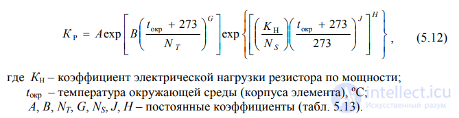

 Values of the coefficient KP are calculated using the model
where KN – resistor power load factor; tokr – ambient (component case) temperature, ºC; A, B, NT, G, NS, J, H – constant coefficients (table 5.13).
Table 5.13 Constant coefficients of model (5.12)
|
Resistor group |
A |
|||
продолжение следует...
Часть 1 5. Models for Predicting the Operational Reliability of Domestically Produced Components
Часть 2 5.7. Switching Elements - 5. Models for Predicting the Operational












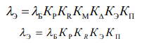




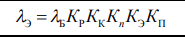










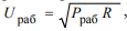 λ, where Pop – operating power, W; R – resistance, Ohm

Comments