
Lecture
When calculating the reliability indicators of devices, it is necessary to have reference data on the reliability indicators of components.
At present, the main reference characteristic of component failure-free operation, given in technical specifications or other technical documents, is the failure rate λ0. The value of λ0 is taken to be constant over a certain operating time, also specified in the technical documentation, and corresponds to the rated electrical mode and normal (laboratory) operating conditions, unless explicitly stated otherwise. Previously (roughly until the 1980s), the quoted values of λ0 characterized the failure-free operation of components only from the standpoint of sudden failures. At present, the values of λ0 given in technical documentation and reliability handbooks characterize the failure-free operation of components with account taken of both sudden and gradual failures [10–12]. The rationale for choosing λ0 as the main reference characteristic of component failure-free operation is given in [1].
Dimension of the failure rate: [λ] = 1/h = h–1.
Reference values of λ0 for modern components lie in the range of roughly 10–10...10–5 1/h.
Abroad, for highly reliable radio-electronic components, the fit has come to be used as the dimension of λ: 1 fit = 10–9 1/h.
The actual level of failure-free operation of components depends on their electrical load factors, defined by the ratio
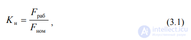
where Frab – the electrical load on the component in the operating mode, i.e. the actual load on the circuit element in question;
Fnom – the rated or limiting electrical load of the component, per the technical specification, performing the function of a circuit element in the design.
As F, an electrical characteristic of the component is chosen that has the greatest influence on its failure-free operation (Table 3.1).
Table 3.1 Electrical Characteristics Used to Determine KN
|
Group of elements |
Characteristic F |
Group of elements |
Characteristic F |
|
1. Resistors |
Dissipated power |
7. Thyristors |
Average forward current, dissipated power |
|
2. Capacitors |
Applied voltage |
8. Transformers |
Power |
|
3. Trimmer varicaps. Transistors, transistor assemblies. Diodes Microwave |
Dissipated power |
9. Chokes, inductors |
Bias current or flowing current |
|
4. Diodes, except zener diodes, diode assemblies |
Average forward current |
10. Relays |
Switched current |
|
5. Semiconductor (SC) alphanumeric indicators, optocouplers, SC emitters |
Average forward current |
11. Connectors, switching elements (switches, toggle switches, buttons, etc.) |
Flowing current |
|
6. Zener diodes |
Stabilization current, dissipated power |
12. Cables, cords, wiring conductors |
Current density in the conductor |
It is not permissible to use elements with an electrical load factor KN > 1 even for just one of the electrical mode parameters. It is considered [1] that for typical RES elements the optimal values of the load factors are KN.opt ≈ 0.2…0.6.
The concept of the load factor of an IC is not directly used in practice. Each IC includes a certain number of elements whose electrical load factors are determined by the internal structure (electrical circuit) and the design/technological features of IC manufacture. The values of the elements' load factors are accounted for by the reference value of the failure rate λ0 of the IC as a whole. The quoted λ0 values correspond to the conditions of a typical (averaged) electrical load on the IC and an ambient temperature of t = +25 ºC. However, in a number of cases some groups (types) of ICs permit operation in lighter modes than the typical ones, for example the use of analog ICs at reduced supply voltage, which increases their operational failure-free operation. The increase in operational failure-free operation (decrease in the operational failure rate) of ICs used in lightened modes can be accounted for by means of the coefficient Kobl, representing the ratio of the operating electrical load to the maximum permissible (rated) load. In this case, the coefficient Kobl can be regarded as a kind of analogue of the load factor KN of the IC as a whole.
In practice, in order to increase the reliability of RED, the load factors of elements KN are chosen to be less than unity. The operating conditions of elements, as a rule, turn out to be more severe than normal. This gives rise to the problem of determining the failure rate corresponding to operational factors (the electrical mode, the operating conditions of the element within the RED, as well as the design/technological features of the element). This failure rate is called the operational failure rate, and we will denote it as λE.
At present, in domestic and worldwide engineering practice, a mathematical model of the following form is widely used to determine λE

where m – the number of factors taken into account out of those influencing the failure-free operation of elements;
Ki – the correction factor accounting for the influence of the i-th factor.
The factors considered include the load factor KN, temperature, the severity of operating conditions, the nature of the electrical mode, the functional purpose of the element in the circuit, the rated value of the element's parameter, and others. For RED operating under ordinary, non-specific conditions, in a number of cases three of the most important factors affecting the value of λE of an element are taken into account: the load factor KN, temperature, and the severity of operating conditions. From the results of experimental studies, mathematical models have been obtained and reference tables compiled for determining the correction factor accounting for the joint influence of KN and temperature. It is called the mode factor KR. The value of the operating-environment factor KE, which accounts for the severity of operating conditions (other than temperature), shows how many times higher the failure rate of elements within a RED of a particular group is compared with equipment operating under stationary laboratory conditions.

Comments