
Lecture
When designing RED, the failure-free-operation indicators and the maintainability indicators are always calculated (if, according to the technical specification, the RED belongs to repairable products).
The basic calculation relation for the probability of failure-free operation of a device is obtained on the assumption that, from the reliability standpoint, the elements of the RED's electrical circuit are connected in series. This reliability model of the RED is illustrated in Fig. 4.1 and means that a failure of the RED as a whole occurs when at least one of the elements fails.
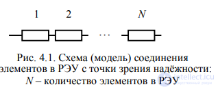
Given the adopted model and the exponential reliability law of the elements, the probability of failure-free
operation of the RED PΣ(tZ) for a specified time

where N – the number of elements in the device;
λi – the parameter of the exponential distribution for the i-th element, numerically equal to the failure rate of that element, i = 1, ..., N.
From expression (4.1) it can be seen that calculating the failure-free-operation indicator PΣ(tZ) reduces to determining the quantity

called the total failure rate of the device.
For the mean recovery time of the RED TV, the following expression can be obtained [1]
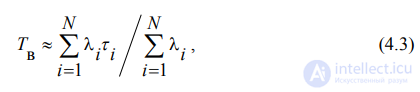
where τi – the mean recovery time of the i-th element (the values of these quantities can be found in reference tables [1] for various types of elements and classes of equipment).
Existing methods for calculating failure-free-operation and maintainability indicators of RED differ in the degree of accuracy with which they account for the electrical mode, operating conditions, and the design/technological, functional and other features of the elements making up the device.
Calculations are divided into preliminary (approximate or estimated) and final.
Approximate calculations are performed at the early stages of design, usually at the preliminary design (PD) stage, while final ones are performed at the detailed design (DD) stage. In practice, various kinds of approximate calculation are used. The simplest one is described in [1]. In this case, accounting for the electrical mode, temperature, other environmental parameters, and factors affecting the operational failure-free operation of elements is done approximately by means of the generalized operating-environment factor KE.GEN. The value of this factor depends on the type of RED and its operating conditions (Table 4.1).
Table 4.1 Values of the Generalized Operating-Environment Factor KE.GEN [1]
|
Type of RED, operating conditions |
Value of KE.GEN |
|
Laboratory conditions |
1.0 |
|
Premises with controlled temperature and humidity |
1.1 |
|
Space (in orbit) |
1.5 |
|
Ground stationary conditions |
2…4.7 (2.5) |
|
Ground vehicle-mounted RED |
4…7 (5.0) |
|
Ground mobile (portable) RED |
7…15 (7.0) |
|
Marine protected conditions |
7…12 (7.6) |
|
Marine unprotected conditions |
7…15 (10.0) |
|
Airborne aircraft RED |
5…10 (7.0) |
|
Rocket launch |
10…44 (20.0) |
Note. The values given in parentheses are those recommended for use in calculations in cases where data on the operating conditions are insufficient.
The total failure rate of the RED, taking into account the electrical mode and operating conditions ΛRED, is determined as

where λo j – the group-average value of the failure rate of the elements of the j-th group, found using reference books, j = 1, …, k;
k – the number of groups of same-type elements formed;
nj – the number of elements in the j-th group, j = 1, …, k.
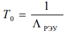
Other failure-free-operation indicators are calculated using the accepted formulas for the exponential distribution of time to failure of the RED (Table 4.2) [1, 4].
Table 4.2 Calculation of Failure-Free-Operation Indicators
|
Failure-free-operation indicator |
Calculation formula |
Formula number |
|
Mean time between failures |
|
(4.5) |
|
Probability of failure-free operation for a specified time tZ |
|
(4.6) |
|
Mean time of failure-free operation of the device (mean time to failure) |
Tavg =T0 |
(4.7) |
|
Gamma-percentile operating time to failure Tγ |
|
(4.8) |
Durability indicators are evaluated once, at any stage of the research and development work (R&D), if this is specified in the contract for the performance of the R&D.
In industry, a variant of the approximate calculation of failure-free-operation and maintainability indicators is used, in which the values of the operational failure rates of elements λE are used at a load factor of KN = 0.7 for active elements and KN = 0.4 for passive elements, and the operating temperature is taken as 35 ºC. When performing a refined calculation, the values of the operational failure rates of elements are determined for the actual values of the electrical load parameters and operating conditions.
In a refined calculation, the total failure rate of the RED in the form of an electronic module (printed circuit assembly) ΛM is determined by summing the predicted values of the operational failure rates of the elements λE:

where λE i – the operational failure rate of the i-th element (component), found taking into account its electrical mode, operating conditions within the RED, and design/technological, functional and other features;
N – the number of elements (components) in the module.
Using the resulting value of ΛM, the failure-free-operation indicators of interest for the module can be calculated using formulas (4.5)–(4.8).
The sequence for calculating the failure-free-operation indicators of a RED consisting of several modules (parts) is described in subsection 7.2.




Comments