
Lecture
Это окончание невероятной информации про .
...
colspan="2">
B
NT
G
NS
J
H
Fixed resistors:
metal-dielectric, metallized
0.260
0.5078
343
9.278
0.878
1
0.886
film composition
0.06
1.616
328
2.746
0.622
1.198
0.770
bulk composition
0.093
2.194
358
2.019
1.245
1.2
1.362
Variable resistors:
non-wirewound cermet
0.399
1.5419
343
9.8965
3.1668
1.3071
0.6012
bulk composition, potentiometers
0.655
0.693
373
7.223
2.895
1
1.335
wirewound
0.202
1.14
343
21.7
0.529
1
0.599
The values of coefficients KM, KR and KU are selected from Tables 5.14–5.16 .
Table 5.14
Values of coefficient KM for metal-film resistors
|
Power, W |
KM |
Power, W |
KM |
Power, W |
KM |
|
0.062–0.5 |
0.7 |
1–2 |
1.5 |
5–10 |
4.5 |
Table 5.15 Values of coefficient KR
|
Resistance range |
KR |
Resistance range |
KR |
Resistance range |
KR |
|
Fixed non-wirewound resistors: metal-film |
|||||
|
< 1 kOhm |
1.0 |
≥ 1 kOhm < 100 kOhm |
0.7 |
≥ 100 kOhm < 1 MOhm |
2.0 |
|
carbon |
|||||
|
≤ 100 kOhm |
|||||
|
Variable resistors: non-wirewound cermet |
|||||
|
> 10 Ohm ≤ 100 Ohm |
1.6 |
> 100 Ohm ≤ 330 Ohm |
1.4 |
> 330 Ohm |
1.0 |
|
wirewound |
|||||
|
≤ 1 kOhm |
1.9 |
> 1 kOhm ≤ 10 kOhm |
0.5 |
> 10 kOhm ≤ 100 kOhm |
0.9 |
Table 5.16
Values of coefficient KU for variable non-wirewound resistors
|
Uop / UTU |
KU |
Uop / UTU |
KU |
Uop / UTU |
KU |
|
≥ 0.1 ≤ 0.8 |
1.0 |
> 0.8 ≤ 0.9 |
1.05 |
> 0.9 ≤ 1.0 |
1.2 |
The values of coefficient KΔ depending on the resistor's resistance tolerance: 2 – for a tolerance of ±0.5 %, 1 – for a tolerance of ±1, ±2, ±5, ±10 % and higher.
The values of KR are calculated using the model

where t – operating temperature, ºC (25 ≤ t ≤ tmax); tmax – maximum permissible ambient temperature per the technical specification; KN – electrical current load factor.
The values of coefficient KK are selected from Table 5.17.
Table 5.17 Values of coefficient KK for switching products
|
Product group |
Number of contacts used N |
KK |
Product group |
Number of contacts used N |
KK |
|
Toggle switches |
Single-pole Double-pole Triple-pole Four-pole |
0.5 1.0 1.5 2.0 |
Push-button and slide switches |
1 |
0.25 |
|
2 |
1.0 |
||||
|
≥3 |
2.0 |
||||
|
Rotary (wafer) switches |
– |
1 |
The values of coefficient KF depending on switching frequency per hour:
KF = 0.5 at F < 100;KF 0.5 0.25lgF at F ≥ 100, (5.14)
where F – product switching frequency in RED, switchings per hour.
The values of KR are determined using the model

where tp – contact overheating temperature per the technical specification at maximum current load, per the technical specification tp = 10…30 ºC;
tamb – ambient temperature, ºC;
KN – electrical current load factor.
The values of the coefficient accounting for the effect of the number of contacts used N on connector reliability can be calculated as
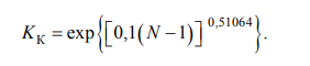 (5.16)
The values of the coefficient accounting for the effect of the number of mating–unmating cycles n on connector reliability are calculated using the model
 (5.17)
The values of coefficient Kt for radio-frequency connectors can be obtained from the expression
 (5.18)
where top – operating temperature of the radio-frequency connector, ºC. The temperature top is determined as [11, 12]
top = tamb + 5, ºC, (5.19)
where tamb – ambient temperature, ºC.
The values of coefficient KR for semiconductor indicators are determined using model (5.8), in exactly the same way as for infrared-range emitting diodes.
The values of coefficient Kt for vacuum fluorescent indicators with a green phosphor can be calculated using the formula
Kt = exp[0.00923(tamb – 25)], (5.20)
where tamb – ambient temperature, ºC.
For other phosphor colors Kt is taken as equal to unity [10–12].
The values of coefficient KR are calculated using the model

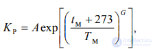 (5.21)
where tm – temperature of the hottest point of the transformer winding, characterized by the insulation class;
A, G, Tm – model constants (Table 5.18).
Table 5.18 Values of the constants of model (5.21)
|
Maximum permissible temperature per the technical specification tmax, ºC (insulation class) |
A |
G |
Tm |
Maximum permissible temperature per the technical specification tmax, ºC (insulation class) |
A |
G |
Tm |
|
70…85 (A) |
0.81 |
15.6 |
329 |
95…105 (B) |
0.891 |
14 |
352 |
The temperature tm is determined as
tm = tamb + tp, (5.22)
where tamb – ambient temperature, ºC; tp – overheating temperature, ºC.
The values of tp for a supply mains frequency f = 50 Hz are calculated using the formula
tp 0.25tp.TU (3Kn2 1) , (5.23)
for f > 50 Hz:
tp 0.5tp.TU (Kn2 1), (5.24)
where tp.TU – maximum overheating temperature per the technical specification, ºC;
KN – electrical power load factor of the transformer. For power transformers of RES: tmax = 85 ºC; tp.TU ≈ 55 ºC.
Chokes, inductors. The values of coefficient KR can be approximately calculated using the mathematical model:
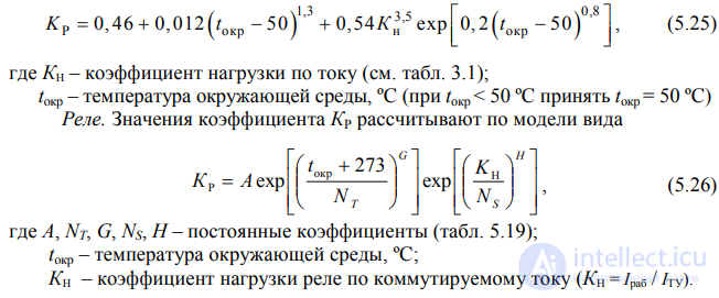
Table 5.19 Values of the coefficients of model (5.26)
|
Maximum permissible relay temperature per the technical specification |
Load type |
|
Coefficient values |
|
||
|
A |
NT |
G |
NS |
H |
||
|
Up to and including 85 ºC |
Resistive |
0.1951 |
352 |
15.7 |
0.8 |
2 |
|
Inductive |
0.4 |
|||||
|
> 85 ºC up to 125 ºC |
Resistive |
0.1919 |
377 |
10.4 |
0.8 |
2 |
|
Inductive |
0.4 |
|||||
The values of coefficient KF depending on the number of relay switchings per hour F when operating as part of RED can be determined as
KF = 0.1 at F ≤ 1, KF = F/10 at F > 1. (5.27)
The values of coefficient KK, accounting for the effect of the number of contacts used N on relay reliability (for non-hermetic relays):
KK = 0.42 + 0.24N. (5.28)
The value (BL) and coefficient KR(L) are determined as for chokes.
Piezoelectric devices. Averaged values of coefficient Kt can be calculated using the model
Kt exp[0.017(tamb 25)], (5.29)
where tamb – ambient temperature, ºC.
Fuses, connections, multilayer boards with metallized through-holes. The values of coefficient Kt are calculated using the model
Kt = 0.061tamb – 0.525, (5.30)
where tamb – ambient temperature, ºC.
Cables, cords, wiring conductors. The averaged value of coefficient Kt is determined using the mathematical model:

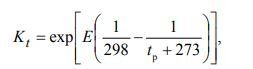 (5.31)
where E – coefficient determined by the insulation material of the cable product, can be taken as [11, 12]: 4570 – for wiring conductors; 9862 – for radio-frequency cables, conductors; 11233 – for power cords;
top – operating temperature, ºC.
The temperature top is made up of two components:
top = tamb + tp, (5.32)
where tp – overheating caused by the electrical or electromagnetic energy dissipated in the cable (conductor).
tamb – ambient temperature;
The values of tp for power cords and wiring conductors can be found as
tp (tmax 25)KN2 , (5.33)
where tmax – maximum operating temperature of the cord, conductor per the technical specification, ºC; KN – electrical load factor.
Coefficient KN is determined as the ratio
KN = j/jmax, (5.34)
where j – operating current density in the conductor, jmax – maximum permissible current density per the technical specification.
In the absence of sufficient data, the current density jmax can be taken as equal to 3.5 A/mm2 [17].
The condition top ≤ tmax must be satisfied. Otherwise the value of KN must be reduced.
The values of the maximum operating temperature tmax for cable products of general-purpose RED are selected from Table 5.20.
Table 5.20
Maximum operating temperature of cables, cords, wiring conductors (tmax)
|
|
Cable product group |
Value of tmax, ºC |
Total cross-section of conductive cores, mm2 |
|||
|
|
1. Low-voltage installation and connecting conductors with polyvinyl chloride (PVC) insulation |
70 |
0.08; 0.12, 0.20; 0.35; 0.5; 0.75; 1.0; 1.5 |
|||
|
2. Low-voltage installation and connecting conductors with insulation of cotton yarn or silk and polyvinyl chloride |
70 |
0.08; 0.12; 0.14; 0.20; 0.35; 0.5; 0.75; 1.0; 1.5 |
|
|||
|
3. Low-voltage installation and connecting conductors with polyethylene (PE) insulation |
85 |
0.08; 0.12; 0.20; 0.35; 0.5; 0.75; 1.0; 1.5; 2.5 |
|
|||
|
4. Low-voltage installation and connecting conductors with two-layer silk polyethylene (PE) insulation |
100 |
0.08; 0.12; 0.20; 0.35; 0.5; 0.75; … |
|
|||
|
5. Power cords with PVC insulation |
70 |
0.35; 0.5; 0.75 |
|
|||
|
6. Power cords with PVC insulation in a PVC sheath |
70 |
0.5; 0.75; 1.0; 1.5 |
|
|||
|
7. Flexible power cords with insulation and sheath of silicone rubber |
100
|
0.75; 1.0; 1.5; 2.5; 4.0 |
|
|||
|
8. Radio-frequency cables with solid PE insulation and in a PE or PVC sheath |
85 |
– |
|
|||
Table 5.21 presents a classification of ground equipment groups depending on operating conditions, compiled by the authors of this textbook with reference to reliability handbooks and standards of Russia, the USA and China [10–13, 15]. It also indicates the approximate correspondence of the identified groups to the Russian military standard and the US reliability handbook. For comparison of ground equipment with equipment of other categories, Table 5.21 also gives (the last two rows) a characterization of operating conditions, and further on the values of KE are given for airborne, in particular aircraft, equipment.
Table 5.21
Classification of Equipment by Operating Conditions
|
|
Symbol of equipment group |
Characteristics of the equipment and its operating conditions |
Approximate correspondence to the group under documents of other countries |
|||||
|
|
GOST RV 20.39.304-98 (Russia) |
MILHDBK- 217F (USA) |
||||||
|
|
Z |
Ground (operated on the ground) equipment, general designation |
1 |
G |
||||
|
|
ZR |
Stationary equipment operated under laboratory conditions, in permanent residential premises, in premises with artificially regulated climatic conditions |
1.1 |
GB |
||||
|
|
ZChR |
Stationary equipment operated in irregularly heated premises (volumes), in industrial, including ventilated underground premises (mine shafts); partial regulation of climatic conditions is possible |
1.1 |
GB,GMS |
||||
|
|
ZOV |
Stationary equipment operated under a canopy or in unheated premises (volumes), where climatic conditions are close to open-air conditions |
1.2 |
GF |
||||
|
ZPN |
Portable equipment operated in stationary-application mode in any premises or under a canopy (under the operating conditions of equipment groups ZR, ZChR and ZOV) |
1.10 |
GF |
|
||||
|
ZM |
Mobile equipment (portable, movable) operated in any premises, including in the bodies and trailers of vehicles, in tents or in the open air |
1.3–1.9 |
GM |
|
||||
|
ZMD |
Mobile equipment operated on railway transport, in the bodies and cabins of automobiles and other mechanical vehicles |
1.3–1.9 |
GM |
|
||||
|
B |
Equipment of aircraft and helicopters, operated in airspace (airborne equipment), general designation |
3 |
A |
|
||||
|
BSK |
Equipment of cargo and passenger aircraft, operated in compartments (cabins, cockpits) where people are present |
3.2 |
AIC |
|
||||
Table 5.22 gives approximate (averaged) values of coefficient KE for the equipment groups indicated in Table 5.21. The averaging of the KE values was done using data from USSR [10] and Russian [11, 12] handbooks, taking into account the Chinese standard [15].
Table 5.22 Values of Coefficient KE
|
Class (group of elements) |
Equipment group depending on operating conditions |
||||||
|
ZR |
ZChR |
ZOV |
ZPN |
ZM |
ZMD |
BSK |
|
|
1. IC |
1 |
1.2 |
1.5 |
1.7 |
2 |
3 |
3.5 |
|
2. Semiconductor devices, including optoelectronic: |
|
|
|
|
|
|
|
|
diodes, except microwave diodes |
1 |
1.2 |
1.5 |
2 |
3 |
4 |
4 |
|
zener diodes, voltage limiters |
1 |
1.2 |
1.7 |
2.5 |
4 |
5 |
5 |
|
microwave diodes |
1 |
1.2 |
1.3 |
1.5 |
2 |
2 |
3 |
|
bipolar transistors, except microwave |
1 |
1.2 |
1.5 |
2 |
4 |
5 |
4 |
|
microwave bipolar transistors |
1 |
1.2 |
2 |
2.5 |
4 |
5 |
5 |
|
field-effect transistors, thyristors |
1 |
1.2 |
1.3 |
1.5 |
1.7 |
2 |
3 |
|
semiconductor emitters (LEDs), optocouplers |
1 |
1.1 |
1.3 |
1.5 |
2 |
2.5 |
6 |
|
photodiodes, photoresistors, phototransistors |
1 |
1.1 |
1.5 |
2 |
3 |
4 |
6 |
|
3. Alphanumeric display indicators (vacuum fluorescent, vacuum incandescent, gas-discharge, semiconductor) |
1 |
1.1 |
1.3 |
1.5 |
2 |
2.5 |
6 |
|
4. Piezoelectric devices, electromechanical filters |
1 |
1.1 |
1, 3 |
1.5 |
1.7 |
2 |
2 |
|
5. Resistors: |
|
|
|
|
|
|
|
|
fixed non-wirewound |
1 |
1.2 |
1,5 |
2 |
3 |
5 |
6 |
|
wirewound and foil fixed |
1 |
1,2 |
1,5 |
2 |
3 |
5 |
10 |
|
variable non-wirewound |
1 |
1,5 |
2 |
2,5 |
4 |
6 |
8 |
|
variable wirewound |
1 |
1,5 |
2 |
2,5 |
4 |
5 |
5 |
|
resistor microcircuits, assemblies |
1 |
1,2 |
1,5 |
2 |
3 |
5 |
6 |
|
thermistors |
1 |
1,2 |
1,5 |
2 |
3 |
5 |
6 |
|
6. Capacitors: |
|
|
|
|
|
|
|
|
ceramic, glass, mica, thin-film with inorganic dielectric |
1 |
1,1 |
1,3 |
1,5 |
3 |
5 |
4 |
|
with organic dielectric, paper |
1 |
1,2 |
1,3 |
1,5 |
3 |
5 |
4 |
|
oxide-electrolytic |
1 |
1,2 |
1,5 |
2 |
3 |
5 |
5 |
|
oxide-porous |
1 |
1,2 |
1,5 |
2 |
3 |
5 |
5 |
|
trimmer |
1 |
1,5 |
2 |
2,5 |
4 |
6 |
5 |
|
7. Transformers |
1 |
1,3 |
1,6 |
2 |
3 |
5 |
10 |
|
8. Chokes, inductors |
1 |
1,3 |
1,6 |
2 |
3 |
5 |
10 |
|
9. Delay lines |
1 |
1,2 |
2 |
3 |
3 |
5 |
10 |
|
10. Switching devices: |
|
|
|
|
|
|
|
|
toggle switches, push-buttons; push-button, rotary (wafer), program and slide switches, reed-based switches |
1 |
1,5 |
2 |
2,5 |
2,7 |
3 |
5 |
|
microswitches |
1 |
1,7 |
2,5 |
3 |
4 |
5 |
10 |
|
magnetically controlled (reed) contacts |
1 |
1,7 |
2,5 |
5 |
10 |
16 |
50 |
End of Table 5.22
|
Class (group of elements) |
Equipment group depending on operating conditions |
||||||
|
ZR |
ZChR |
ZOV |
ZPN |
ZM |
ZMD |
BSK |
|
|
11. Low-frequency connectors |
1 |
1,2 |
1,3 |
1,5 |
2 |
3 |
3 |
|
12. Radio-frequency connectors |
1 |
1,2 |
1,3 |
1,5 |
2 |
3 |
3 |
|
13. Relays: |
|
|
|
|
|
|
|
|
medium-power and low-current electromagnetic |
1 |
1,5 |
2,5 |
4 |
5 |
6 |
8 |
|
protective relays and circuit breakers, automatic switches and disconnectors, etc. |
1 |
1,1 |
1,3 |
1,5 |
1,7 |
2 |
4 |
|
14. Electrical cables, cords, wires |
1 |
1 |
1,2 |
1,5 |
2 |
3 |
7 |
|
15. Connections (soldering, welding, twisting, etc.) |
1 |
1,2 |
1,7 |
2 |
3 |
4 |
5 |
|
16. Soldered joints on boards with metallized holes |
1 |
1,2 |
1,7 |
2 |
3 |
4 |
5 |
|
17. Mounting components (fuses, fuse holders) |
1 |
1,2 |
1,7 |
2 |
4 |
8 |
9 |
|
18. Other elements: |
|
|
|
|
|
|
|
|
cathode-ray tubes |
1 |
1 |
1,3 |
1,5 |
1,7 |
2 |
4 |
|
indicator lamps |
1 |
1,2 |
2 |
3 |
3,5 |
4,5 |
6 |
The acceptance factor KP takes into account the following types of acceptance of elements under production conditions:
elements produced to order for ministries and agencies;
Averaged values of the coefficient KP depending on the type of acceptance of elements of various classes and groups are given in Table 5.23. For elements with acceptance “5” the value of KP is taken as 1. For other types of acceptance, approximate (extrapolated) values of KP were determined from the data in
[10–13, 15, 16].
Table 5.23 Values of the coefficient KP
|
Class (group) of elements |
Values of KP for types of acceptance: |
|
|||||
|
unknown type of acceptance (quality level) |
QCD |
“5” (VP, OVP) |
“7” (OSM) |
“9” (OS) |
|||
|
“1” |
“3” |
||||||
|
plastic packages (for semiconductor devices [PPP] only) |
– |
||||||
|
1. IC |
10 |
– |
5,5 |
3,1 |
1 |
0,5 |
0,3 |
|
2. Semiconductor devices (PPP), including optoelectronic: |
|
|
|||||
|
LF diodes (general-purpose, switching, rectifier, zener diodes, etc.) |
10 |
8 |
5,5 |
2,4 |
1 |
0,7 |
0,35 |
|
microwave diodes, except Schottky diodes |
50 |
50 |
25 |
5 |
1 |
0,6 |
0,6 |
|
microwave Schottky diodes |
|
– |
2,5 |
1,8 |
1 |
0,5 |
0,5 |
|
transistors: bipolar, Si field-effect, unijunction |
10 |
8 |
5,5 |
2,4 |
1 |
0,7 |
0,35 |
|
microwave transistors, bipolar and field-effect, including gallium arsenide |
10 |
– |
5 |
2 |
1 |
0,5 |
0,35 |
|
transistors: LF low-noise, HF (f > 400 MHz), Si field-effect |
10 |
– |
5 |
2 |
1 |
0,5 |
0,35 |
|
Si thyristors |
10 |
8 |
5,5 |
2,4 |
1 |
0,7 |
0,2 |
|
optoelectronic semiconductor devices (PPP) |
10 |
8 |
5,5 |
2,4 |
1 |
0,7 |
0,6 |
|
3. Character-forming (segment) indicators: |
|
|
|||||
|
semiconductor |
10 |
8 |
5,5 |
2,4 |
1 |
0,7 |
0,6 |
|
fluorescent (vacuum-fluorescent) |
4 |
– |
2 |
1,5 |
1 |
– |
– |
|
incandescent |
5 |
– |
3 |
2 |
1 |
– |
– |
|
gas-discharge |
4 |
– |
2 |
1,5 |
1 |
0,8 |
0,8 |
|
liquid-crystal digital |
10 |
– |
5,5 |
3 |
1 |
– |
– |
|
4. Piezoelectric devices: quartz resonators other devices |
10 10 |
– – |
9 4 |
3 2 |
1 1 |
– 0,7 |
– 0,7 |
|
5. Resistors: |
|
|
|||||
|
variable non-wirewound, composition and film |
10 |
– |
5 |
3 |
1 |
0,8 |
0,8 |
|
non-wirewound potentiometers |
10 |
– |
5 |
3 |
1 |
– |
– |
|
the remaining fixed and variable resistors |
10 |
– |
3 |
2 |
1 |
0,5 |
0,3 |
|
6. Capacitors |
10 |
– |
5 |
3 |
1 |
0,5 |
0,3 |
|
7. Transformers: |
|
|
|||||
|
power supply (mains) |
30 |
– |
20 |
10 |
1 |
0,5 |
0,2 |
|
HF (radio-frequency) |
20 |
– |
10 |
5 |
1 |
0,5 |
0,2 |
|
LF, audio |
10 |
– |
5 |
3 |
1 |
0,4 |
0,2 |
|
pulse |
10 |
– |
4 |
2 |
1 |
0,3 |
0,2 |
|
8. Chokes, inductors: |
|
|
|||||
|
all chokes except power chokes |
10 |
– |
5 |
3 |
1 |
0,5 |
0,2 |
|
power chokes |
20 |
– |
10 |
5 |
1 |
0,5 |
0,2 |
|
inductors (coils) |
10 |
– |
5 |
3 |
1 |
0,5 |
0,2 |
|
9. Delay lines |
5 |
– |
4 |
2,1 |
1 |
0,5 |
0,2 |
End of Table 5.23
|
Class (group) of elements |
Values of KP for types of acceptance |
||||||
|
unknown type of acceptance (quality level) |
QCD |
“5” (VP, OVP) |
“7” (OSM) |
“9” (OS) |
|||
|
“1” |
“3” |
||||||
|
plastic packages (for semiconductor devices [PPP] only) |
– |
||||||
|
10. Switching devices: |
|
||||||
|
toggle switches, push-button switches |
15 |
– |
3 |
2 |
1 |
0,5 |
0,2 |
|
rotary (wafer) switches |
15 |
– |
3 |
2 |
1 |
0,5 |
0,2 |
|
circuit switches, circuit breakers (manual and automatic, magnetic, thermal, etc.) |
15 |
– |
8,4 |
3 |
1 |
0,5 |
0,2 |
|
11. LF connectors |
5 |
– |
2,5 |
1,5 |
1 |
0,5 |
0,5 |
|
12. Radio-frequency connectors |
5 |
– |
2,5 |
1,5 |
1 |
0,5 |
0,5 |
|
13. Relays |
9 |
– |
3 |
1,5 |
1 |
0,5 |
0,2 |
|
14. Wiring cables, cords, wires |
5 |
– |
2 |
1,5 |
1 |
0,8 |
0,8 |
|
15. Connections: |
|
||||||
|
solder joints (soldering with solder) |
– |
– |
5 |
3 |
1 |
1 |
1 |
|
welding |
– |
– |
20 |
5 |
1 |
1 |
1 |
|
16. Soldered joints on PCBs with metallized holes |
– |
– |
5 |
3 |
1 |
1 |
1 |
|
17. Fuses, fuse holders |
20 |
– |
15 |
7 |
1 |
0,5 |
0,2 |
|
18. Receiving CRTs, except non-storage oscillographic |
5 |
– |
3 |
2 |
1 |
– |
– |
|
19. Receiving CRTs, non-storage oscillographic |
5 |
– |
3 |
2 |
1 |
0,8 |
0,8 |
|
20. Picture tubes (kinescopes) |
5 |
– |
3 |
2 |
1 |
– |
– |
|
21. Indicator lamps |
5 |
– |
3 |
2 |
1 |
1 |
1 |
Часть 1 5. Models for Predicting the Operational Reliability of Domestically Produced Components
Часть 2 5.7. Switching Elements - 5. Models for Predicting the Operational
 0.5
 > 100 kOhm ≤ 1 MOhm

Comments