
Lecture
Requirements for the failure-free-operation and maintainability indicators of electronic devices may vary depending on the specific operating conditions and purposes of using these devices. However, in general, some basic requirements for reliability and maintainability can be formulated as follows:
Reliability: Electronic devices must be designed and manufactured in such a way as to minimize the probability of failures occurring during operation. This is achieved by using high-quality components, reliable connections, and thorough testing of devices before release.
Durability: Devices must have sufficient durability to last the required time without a significant decrease in their characteristics. This means that they must be designed with regard to the requirements of a long service life, and measures must be provided to prevent wear, corrosion and other factors that can lead to a decrease in operability.
Modularity: Devices should, where possible, be modular, i.e. have separate functional blocks that can be replaced or updated independently of one another. This facilitates the repair and servicing of devices, since only the damaged or obsolete module can be replaced without affecting the other components.
Availability of spare parts: To ensure the maintainability of devices, it is important that spare parts be available for replacing damaged components. Manufacturers must supply spare parts or support the possibility of repairing devices for an acceptable period after their release.
Availability of documentation: Manufacturers must provide detailed documentation, including diagrams, operating and repair manuals, specifications, and other information necessary for the effective servicing and repair of devices.
Testing and diagnostics: Devices must have built-in means for diagnostics and testing that allow problems to be quickly detected and isolated. This helps speed up the repair and servicing process, and also increases the reliability of devices.
These are only some of the general requirements for the failure-free-operation and maintainability indicators of electronic devices. The specific requirements may differ depending on the industry, the type of device, and its purpose.
In the assignment for course or diploma design, the requirements for the reliability indicators of the RED being designed or modernized must be clearly specified. In most cases, the customer (project supervisor) formulates general reliability requirements, for example in the form of the entry: “requirements for reliability indicators per GOST 27.003–90”. It is the student's task to choose the set of specified indicators, establish their numerical values, and coordinate them with the project supervisor in the order accepted at the university.
The indicators should, as a rule, be chosen from among those whose definitions are given in GOST 27.002–89. It is permitted to apply indicators whose name and definition specify the corresponding terms established by GOST 27002–89, taking into account the features of the product and (or) the specifics of its application, but which do not contradict the standardized terms. An example of such an indicator: the probability of an electronic apparatus (as part of a process installation) performing its task during a shift. The total number of specified indicators should be minimal, but should characterize all stages of RED operation: use for its intended purpose, storage, transportation, maintenance, repair, etc.
Let us explain the procedure for specifying requirements for reliability indicators using the example of failure-free-operation and maintainability indicators.
The choice of the set of reliability indicators is made on the basis of classifying products according to features characterizing their purpose, the consequences of failures and the attainment of a limiting state, the features of the modes of application, etc. The classification features of a product are determined through engineering analysis and coordination of its results with the supervisor. The main source of information for such an analysis is the technical specification for the development or modernization of the product, in terms of the characteristics of its purpose and operating conditions, and data on the reliability of analogous products. The main classification features and the division of products into types when specifying reliability requirements are presented in Table 7.1.
Table 7.1 Classification of Products When Specifying Reliability Requirements
|
Classification feature |
Type of product |
|
1. Definiteness of purpose |
Products of specific purpose (PSP), examples: mobile phone, digital camera, music center, portable radio station, etc. Products of general purpose (PGP), example: universal computer, microprocessor control unit, etc. |
|
2. Mode of application |
Continuous long-term application (CLTA) Multiple cyclic application (MCA) Single application (with a preceding period of waiting for application and storage) – SAWS |
|
3. Number of possible states of operability |
Products of type I: during operation can be in one of two states – operable or inoperable Products of type II: besides the operable or inoperable state, can be in partially inoperable states, into which they pass as a result of a partial failure |
|
4. Possibility of restoring the operable state after a failure |
Repairable Non-repairable |
|
5. Need for maintenance during operation |
Serviced Unserviced |
The scheme for choosing the set of failure-free-operation and maintainability indicators, taking into account the classification features, is given in Table 7.2.
Table 7.2 was compiled with regard to GOST 27003–90, which is mandatory for products developed on order from the Ministries of Defense and recommended for other products. Therefore, by agreement with the project supervisor, when choosing failure-free-operation and maintainability indicators, deviations from the guidance of Table 7.2 are possible.
The electronic devices considered within the framework of course and diploma design usually belong to PSP with an MCA or CLTA mode of application. For such devices, it is best to choose T0 and TV (repairable products) or Tavg (non-repairable products) as the failure-free-operation and maintainability indicators. The failure-free-operation indicator P(tZ) for the electronic devices in question is advisable to choose in the case where it is fundamentally important for the device to perform some task during a continuous operating time (the duration of performing a typical technological process, the duration of solving a typical task, for example monitoring airspace during aircraft landing, etc.).
Table 7.2 Recommendations for Choosing the Set of Failure-Free-Operation and Maintainability Indicators for Type I Products
Classification of products by features determining the choice of a reliability indicator
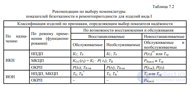
Note. T0 – mean time between failures (operating time to failure); KG – availability factor; P(tZ) – probability of failure-free operation for a specified time tZ; KO.G(tZ) – operational availability factor over time tZ; P0(on) – probability of failure-free switch-on; TV.wait – mean recovery time in standby mode; Tavg – mean time of failure-free operation; Tγ – gamma-percentile operating time to failure; P(twait) – probability of failure-free operation during the waiting time twait.
Example of recording reliability requirements in the assignment for diploma design. The reliability of _____________ under the operating conditions and modes,
(name of the RED)
specified in items _____ of the design assignment, must be characterized by
the following indicator values:
mean time between failures – not less than 5000 h;
mean recovery time at the operating site – not more than 1.0 h.
At the instruction of the project supervisor, an instruction may be given to calculate other failure-free-operation indicators, the requirements for which are not established in the
design assignment (for example, the gamma-percentile operating time to failure).
In course and diploma projects of the specialties "Modeling and Computer-Aided Design of RES" and "Design and Production of RES", a refined calculation of failure-free-operation indicators should, as a rule, be provided for, and, if necessary, also of the maintainability indicators of the RED being designed or modernized.
In the case of complex RED (two or more units, modules, etc.), the procedure for predicting their reliability by the calculation method is determined by GOST 27.301–95. Constituent parts of the RED are identified – modules, usually at the level of printed circuit assemblies. A separate independent part is made up of the supporting structure with switching and control elements, inter-unit wiring, and ERI not included in the printed circuit assemblies. The failure-free-operation indicators of the functional parts (modules) are calculated and, using these indicators, the failure-free operation of the RED as a whole is evaluated.
The main source data for the calculation are:
Recommended sequence for calculating the failure-free-operation indicators.
Within the RED under consideration, functional parts are identified which, from the reliability standpoint, will be treated as independent.
For each (the i-th) identified part (module), the following actions are performed in sequence.
1. Using the parts lists and (or) specifications, and if necessary the technical documentation for the elements, their electrical and operational characteristics needed for choosing or calculating the correction factors used in the mathematical models for calculating (predicting) the operational failure rate of elements are ascertained. For ICs, it is necessary to at least approximately determine the number of elements within the IC or the number of bits (for memory ICs).
2. Using electrical mode maps or by the express-analysis method for electrical circuits, the load factors of the elements are found. An error of up to 20% is allowed. If some IC operates in a de-rated (lightened) mode, then the mode de-rating factor Kobl is calculated (see subsect. 3.2).
3. The maximum possible temperature of the elements when operating as part of the REE is determined: for heat-loaded elements – taking into account the value tZ, for non-heat-loaded elements – taking into account the value tV.
4.The operational failure rate λE of elements manufactured in CIS countries is estimated. For this, the following is done sequentially for each element:
5.Using the information from sect. 6, the calculation (prediction) of λE of foreign-made elements is performed.
6.If the printed circuit board has metallized holes, then its operational failure rate is determined using the model given in Table 5.1, taking into account the number of soldered joints of the metallized holes.
7.The operational failure rate of soldered connections on the printed circuit board is determined for holes where there is no metallization.
8.By simple summation of the λE values of the elements and components, the operational failure rate of the i-th functional part (module) ΛEi is calculated; i = 1, …, N , where N – is the number of modules.
When calculating the value ΛEi elements of the same functional purpose
with identical electrical modes, structural-technological and other factors may be combined into groups of same-type elements. In this case, the value ΛEi for the i-th module is determined by the expression

where λE j – is the operational failure rate of the elements of the j-th group;
nj – is the number of elements in the j-th group; in the limiting case there may be only one element in each group;
k– is the number of formed groups of same-type elements.
For soldered connections on the printed circuit board for holes where there is no metallization, the number of elements in the j-th group is always greater than one (nj > 1).
The operational failure rate of the REE as a whole is determined by summing the values ΛE i:
|
ΛREE = ΛE1 + ΛE2 + ...+ ΛEN . |
(7.2) |
If the REE contains identical modules, then to calculate the value ΛREE, instead of (7.2) the expression may be used

where mi – is the number of modules of the i-th type in the REE;
v– is the number of module varieties.
Assuming an exponential reliability law, using formulas (4.5)–(4.8) the calculated values of other failure-free operation indicators of the REE are found.
Let us consider a refined calculation of the failure-free operation indicators of a functional module made using printed-circuit mounting. The printed circuit board is two-layer with metallized through-holes. The total number of holes on the printed circuit board is 853, of which 505 holes are metallized. The electrical connection of the module to the REE, as part of which it will function, is carried out by means of an SNP34-type connector. The quality level of the elements (components) used in the module corresponds to acceptance “1” – QCD acceptance. The module is intended for operation as part of mobile equipment of design category UKhL 2.1 per GOST 15150–69
.The specified operating time, indicated by the customer, is tr = 1000 h. The failure-free operation indicators of interest – T0, P(tr) and Tγ at γ = 95%.
We assume that we have at our disposal maps of the electrical operating modes of the module elements and the results of the thermal calculation of the REE, as part of which the module will function:
We assume that the circuit design solution of the module is such that the ICs operate in typical electrical modes, and the information on the elements (components) included in the module corresponds to Table 7.3.
Table 7.3 Elements and Components Included in the Module
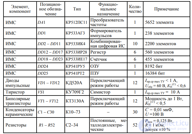
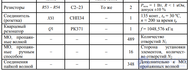
Notes: 1. The packages of the ICs and semiconductor devices (PPP) used are plastic; the IC manufacturing technology is non-CMOS.
2.The table uses intuitively understandable designations of parameters characterizing the operational capabilities and electrical operating mode of the elements.
3.Accepted abbreviation: MH – metallized holes in the printed circuit board.
Calculation Stages
Stage 1. We find the load factors of the elements, using the electrical mode maps and the operational electrical characteristics of the elements used in the module. We assume that the data obtained correspond to the values given in Table 7.4.
Stage 2. We determine the maximum temperature of the module elements during its operation as part of the REE. To account for the influence of temperature on the operational failure rate of the elements λE, the upper value of the limiting operating temperature (top max = +45 °C), corresponding to REE design UKhL 2.1 per GOST 15150–69, is taken into account, as well as the possible increase in the limiting operating temperature by the value tS = 10 °C due to heating (by sunlight) of the REE and, consequently, of the module as part of the REE (see item 5.4 of GOST 15150–69).
The limiting operating temperature tel max of heat-loaded elements (ICs, transistors, diodes, high-power resistors) is determined as
tel max = (top max + tS ) + tZ = (45 + 10) + 15 = 70 °C,
where tZ – is the overheating in the heated zone of the REE structure.
The heated zone – is a hypothetical volume in which all the thermal energy released by the REE elements is conventionally dissipated.
The value of tel max for non-heat-loaded elements (capacitors, lightly loaded resistors, connector, crystal resonator) is calculated as
tel max = (top max + tS ) + tV = (45 + 10) + 10 = 65 °C,
where tV – is the average air overheating inside the REE structure.
Table 7.4
Calculation of the Operational Failure-Free Operation of the Module Elements
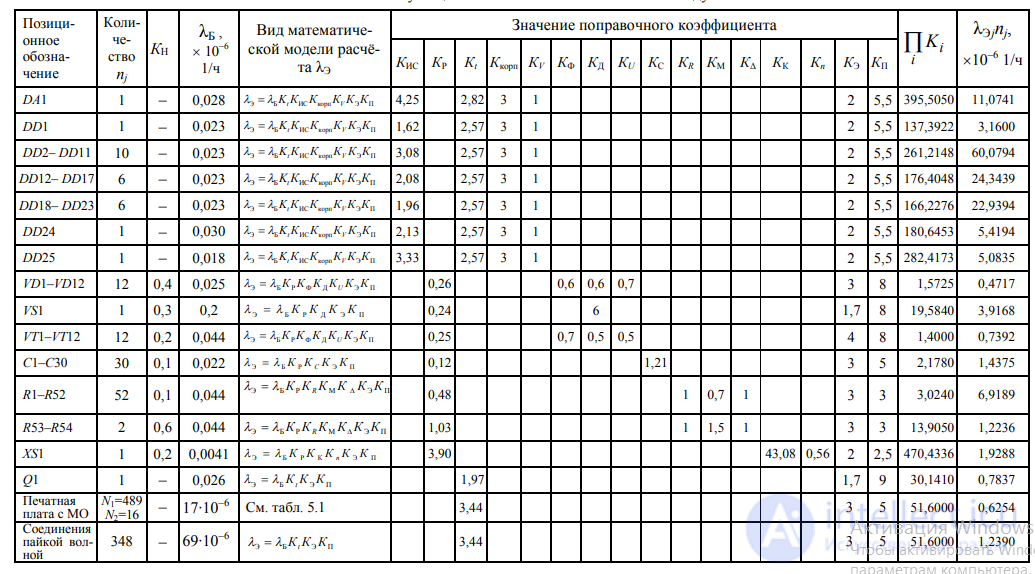
Note. In the last column, the value 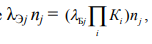 , where i indicates the factor taken into account, j – the group of same-type elements.
Stage 3. Using Table 5.3, we find the reference values of the failure rates of the module elements. The data obtained are entered in Table 7.4.
Stage 4. Using Table 5.1, we select the mathematical models for calculating the operational failure rate of the elements λE. The selected models are recorded in Table 7.4.
Stage 5. We determine the values of the correction factors included in the selected models for calculating the operational failure rate of the elements λE. The numbers of the formulas or tables used to determine the correction factors are found from Table 5.1 depending on the class (group) of the module elements. For example, for calculating the coefficients KIS of integrated circuits, model (5.3) and Table 5.4 were used.
The found values of the correction factors are recorded in Table 7.4. Stage 6. For each element we find the product of the correction factors and the value of the operational failure rate λE. For convenience of calculation, elements of the same functional purpose with approximately identical electrical modes, structural-technological and other factors are combined into one group. The value of the total operational failure rate of the group elements (λEΣ) is obtained as

where λE j – is the operational failure rate of the elements of the j-th group; nj – is the number of elements in the j-th group (see Table 7.3).
If there is one element in the group (nj = 1), then for it λEΣ = λEj.
The results of the stage calculations are entered in the last two columns of Table 7.4. Stage 7. We determine the operational failure rate of the printed circuit
board taking into account, jointly with the metallized holes, using the model given in Table 5.1. The values of the coefficient Kt are determined by expression (5.30) at the value tenv = 65 °C (see stage 2). Considering that for single- and double-sided printed circuit boards the coefficient Ksl = 1, we obtain
λE = 0,000017⋅10–6 ⋅ [489⋅1 + 16(13+1)] ⋅ 3,44⋅3⋅5 ≈ 0,6254⋅10–6 1/h.
The model used for the calculation applies only to connections (soldered joints) in metallized holes. Soldered joints on the printed circuit board in non-metallized holes must be accounted for separately.
The printed circuit board as a component of the module structure forms a separate group, for which λEΣ = λE. The value is entered in the last column of Table 7.4.
Stage 8. We determine the total operational failure rate of wave-soldered connections for holes where there is no metallization, and enter the result in the last column of Table 7.4:
λEΣ = 348⋅ λB Kt KE KP = ⎮ λB = 0,000069⋅10–6 1/h (see Table 5.3)⎮= 348 ⋅ 3,44 ⋅ 0,000069⋅10–6 ⋅ 3 ⋅ 5 ≈ 1,2390 ⋅10–6 1/h.
Stage 9. We calculate the operational failure rate of the module (ΛM). For this we sum the values given in the last column of Table 7.4:

Stage 10. Assuming an exponential reliability law, we find the calculated values of other failure-free operation indicators:
a) mean time between failures:
T0 = 1/ΛM ≈ 6605,7 h;
b) probability of failure-free operation over time tr = 1000 h:
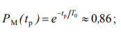
c) gamma-percentile operating time to failure at γ = 95% :

Note. For the printed circuit board, a model accounting for soldered joints of through metallized holes was used. The calculation of the operational failure rate of the printed circuit board itself, taking into account its area and the predominant width of the printed conductors, should be carried out using separate models, which are not considered in this manual.
The training system for automated calculation and optimization of the reliability of electronic devices (US ARION) is a modular software system that allows the evaluation (prediction) of the failure-free operation indicators of electronic devices at the level of units and modules, based on data on the reliability of elements, their electrical operating modes and conditions. The mode of user interaction with the PC – is interactive. US ARION includes a database of generalized failure-free operation indicators of various classes and groups of elements manufactured in CIS countries, as well as information needed to determine the values of the correction factors. US ARION contains a module for working with foreign-made elements (integrated circuits, semiconductor devices, optoelectronic semiconductor devices, resistors and capacitors).
The range of reliability indicators to be determined using the system – is the failure-free operation indicators of electronic devices in the operating mode according to GOST 27.002–89 .
A feature of the software system is the graphical display of the contribution of classes, groups and even individual elements (components) to the overall unreliability of the device. This allows the software system to be used to purposefully and effectively solve problems of ensuring the failure-free operation indicators of devices.

Comments