
Lecture
Reliability is understood as the property of a product to retain, over a given period of time and within established norms, the values of its functional parameters under specified conditions (given operating modes and conditions of use, maintenance, storage and transportation).
In the theory and practice of reliability of technical products the concept of operating time is widely used, meaning the duration of operation of a product, expressed in hours, switching cycles or other units depending on the type and functional purpose of the product.
Evaluation of the reliability indicators of radio-electronic devices (RED) is a mandatory procedure carried out at the equipment design stage. The relevance of reliability-calculation tasks is explained by the fact that they answer the question of whether it is worthwhile to continue spending resources on developing the technology and manufacturing radio-electronic devices. Therefore, assignments for graduation design projects of a design and technology profile include the study of questions on evaluating the reliability indicators of RED.
The curricula of the specialties “Modelling and Computer-Aided Design of Radio-Electronic Equipment” and “Design and Manufacture of Radio-Electronic Equipment” include a discipline that covers the fundamentals of the theory and methods for evaluating the reliability indicators of RED. The skills and knowledge students gain regarding the reliability of radio-electronic products will be fully applicable in graduation design projects.
At present design and manufacturing enterprises experience difficulties in calculating the reliability indicators of RED because of incomplete data on the reliability indicators of components produced in CIS countries, the lack of data on components of foreign manufacture that are part of electronic devices, and also because of the lack of a system, adapted to these conditions, for automated calculation of the reliability indicators of devices. Having such a system would substantially reduce the time needed to solve the task of evaluating the reliability of electronic devices under the conditions indicated.
The manual contains educational material on evaluating the failure-free operation indicators of RED as the most important group of quantitative reliability indicators. The basis for calculating the failure-free operation indicators of RED is formed by mathematical models for calculating (predicting) the operational failure-free performance of components. The share of components from far-abroad countries in equipment of domestic manufacture exceeds 50%, therefore the authors considered it appropriate to include in the manual models for predicting the operational failure-free performance of components manufactured both in CIS countries and in far-abroad countries. In refining and describing the models, reference handbooks on reliability developed in the Russian Federation were used, as well as reference handbooks and standards for predicting the reliability of electronic equipment currently used in the USA, China, France and the United Kingdom.
In systematizing the methodology for calculating the failure-free operation indicators of RED, the results of R&D work on developing an industrial system for automated calculation and optimization of the reliability of electronic devices – ARION – carried out by the Department of Radio-Electronic Equipment of the Belarusian State University of Informatics and Radioelectronics were used.
also set out are certain provisions of reliability theory and the principles for calculating the operational failure rate of components and evaluating the failure-free operation indicators of RED as a whole.
The reliability of radio-electronic equipment is connected with random events and quantities, such as failure and time to failure. To quantitatively determine reliability a statistical assessment of the quality of the device is used.
For complex systems and complexes, before evaluating their reliability, clear definitions are given of what is to be considered a malfunction and what is to be considered a failure. In doing so, account may be taken of the fact that, depending on the functional structure of the system, the failure of some auxiliary units and blocks may not lead to the failure of the system as a whole. For simple devices, when calculating reliability it is customary to consider that the failure of any component included in it leads to the failure of the whole device.
Although this article focuses on questions of the reliability of power electronics, most of the material of the article holds true for other radio-electronic equipment as well.
The starting point for the quantitative determination of reliability parameters is the probability distribution of failure over time. To evaluate this distribution, a certain number of products are operated for a long time and the moments at which each of these products fails are recorded. If at the first moment in time all 100% of the products are operable, then by some moment in time (in principle, this may even be at t→∞) all the products will have failed. The normalized curve, built on the basis of a large number of measurements, characterizes the probability density of failure over time f(t). Using the probability density f(t), other reliability characteristics of the components are found, namely: the probability of failure of the components in the time interval from t to t+Δt, the probability of failure-free operation of the component over time t, the mean service life of the components, the failure rate of the components, determined as the fraction of components failing per unit time relative to their quantity at moment t, the frequency of failures of the components (defined as the fraction of components failing per unit time relative to their initial quantity), the mean frequency of failures of the components.
One of the factors determining the overall reliability of a device is the reliability of the components included in it: resistors, capacitors, diodes, transistors, transformers, integrated circuits (ICs) and so on. The failure of any of these components or a change in their parameters beyond certain limits will lead to the failure of the whole product.
For most components of radio-electronic equipment the dependence of λ on time has the form of a U-shaped curve (Fig. 1).
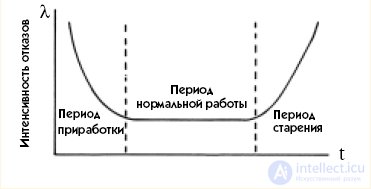
Fig. 1. Dependence of the change in failure rate on time
In the first period of time, called the burn-in period, components with gross defects not detected by inspection fail. After these components are identified the failure rate decreases and then remains constant, and the period of normal operation begins. As the components wear, the failure rate rises again, and the period of ageing of the components begins.
*
Depending on the context, the abbreviations given may be used in the singular or plural.

Comments