
Lecture 30 min.
Probing signals are specially generated electromagnetic signals used to investigate or probe a medium or objects in order to obtain information about their properties or structure. They can be used in various fields such as radar, medical diagnostics, geophysics, seismology, and others.
Probing signals usually have known characteristics and are chosen specifically for particular investigation tasks. They may be continuous (continuous-wave) or pulsed (pulse-wave) and may have various frequencies, shapes, durations, and amplitudes depending on the task at hand.
The use of probing signals makes it possible to obtain information about various parameters of a medium or objects, such as range, size, shape, composition, electrical properties, motion, and others. The reflected, scattered, or transmitted signal obtained after the interaction of the medium or object with the probing signal is analyzed to extract information and solve the tasks at hand.
Examples of probing signals include radar pulses, medical ultrasound signals, seismic waves, radio-frequency signals in wireless communications, radar, and others. Probing signals are an important tool for investigating and diagnosing various systems and phenomena, as well as for obtaining information about unknown or inaccessible objects and media.
Depending on their purpose, radar systems employ various types of probing signals:
The choice of a particular type of probing signal depends on the nature of the tasks solved by the radar system and the conditions of its operation.
Air defense radar (radar of the Radio Technical Troops), like most radars of other purposes, uses pulsed probing signals.
The use of pulsed probing signals makes it possible to:
The main parameters of probing signals are:
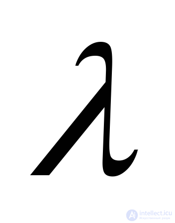 (carrier frequency of oscillations
 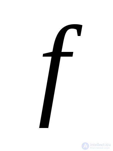 );
); (average power over the repetition period
  );
);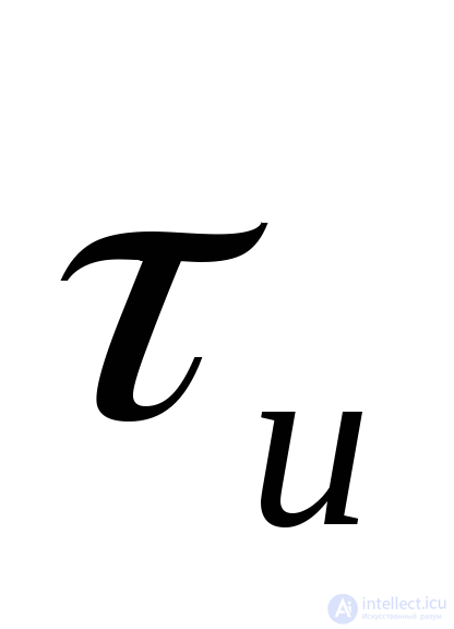 ;
;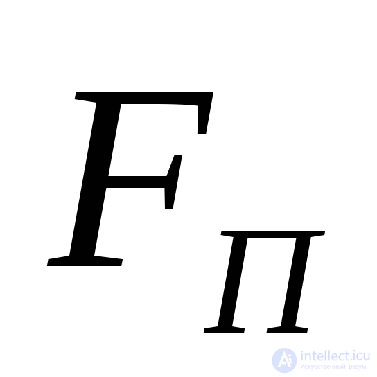 (
(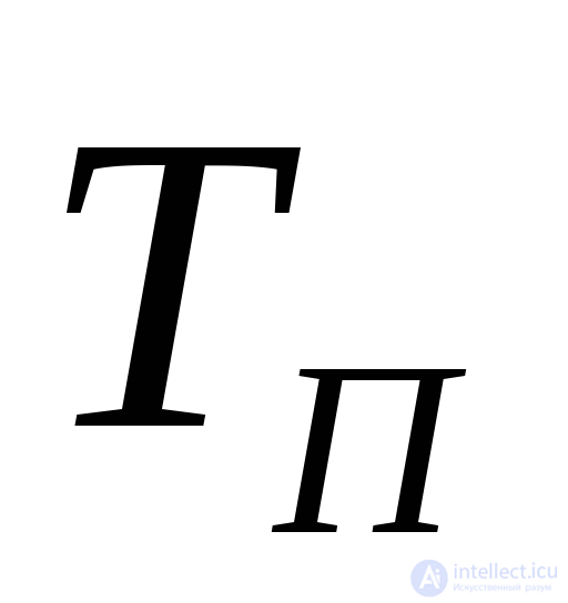 );;
);;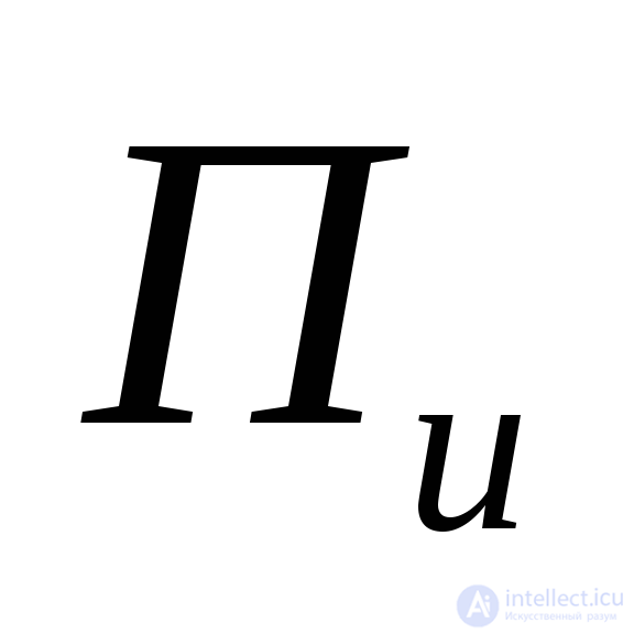 .
.In terms of structure, probing radio pulses can be:
Single radio pulses are, as a rule, not used. Target detection and measurement of its coordinates are usually performed by analyzing a group of radio pulses reflected from the target — a "burst" containing M signals.
Radio pulses are called non-coherent if the initial phase of the high-frequency oscillations is a random variable from pulse to pulse.
Radio pulses are called coherent (from the Latin "cohaerentia" — cohesion, connection) if the initial phase of the oscillations of each radio pulse is the same or changes from pulse to pulse according to a certain law.
Simple (or narrowband) radio pulses are those for which the product of the spectrum width 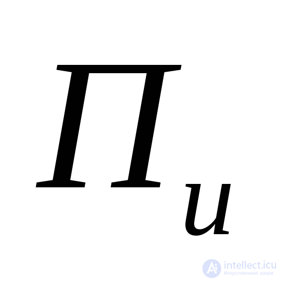 and the pulse duration
 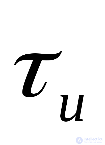 is of the order of unity:
 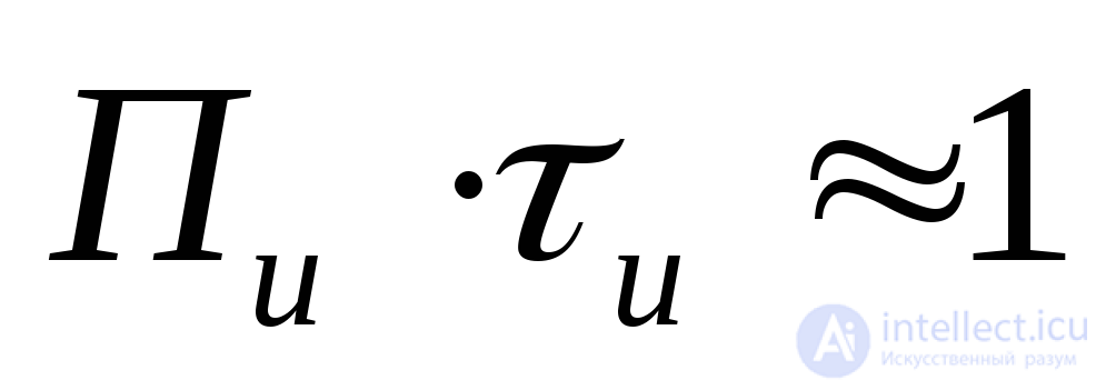 . A pulse signal is called complex (or wideband) if this product, called the signal time-bandwidth product, is
 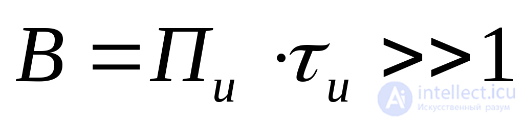 .
.
The advantage of narrowband signals is the relative simplicity of their generation and optimal processing. Narrowband pulses are generated by comparatively simple pulse modulation of a microwave oscillator. Processing of the received echo signals is also comparatively simple, since the quasi-optimal filter is the intermediate-frequency amplifier of the receiver with a matched passband width: 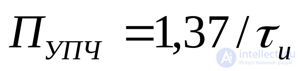 . Compared with the optimal filter, such a quasi-optimal filter gives a loss in signal-to-noise power ratio of only a factor of 1.2.
Simple probing signals are still widely used in pulsed radars today (in older-generation radars) owing to the simplicity of the technical implementation of the generation and processing devices.
However, simple probing signals have significant drawbacks that limit the tactical and technical characteristics of the radar.
In recent years, radars have increasingly employed complex probing signals, mainly of two types:
radio pulses with intrapulse frequency modulation, in particular linear frequency modulation (LFM) or nonlinear frequency modulation (NLFM);
radio pulses with phase-shift keying, in which the phase of the oscillations within the pulse changes abruptly by 180° at certain time intervals. Since these abrupt phase changes follow a certain binary code, such pulses are called phase-coded (PSK) pulses.
Compared with simple radio pulses, the generation and processing of complex radio pulses is a more difficult task, but the use of such signals makes it possible to significantly improve the performance characteristics of the radar.
Let us consider the influence of the characteristics, parameters, and structures of probing radio pulses on the tactical and technical characteristics of air defense radars.
It is known that the maximum radar range in the absence of intentional jamming is determined by the relation:
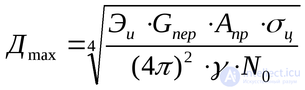 (3.3)
(3.3)
where 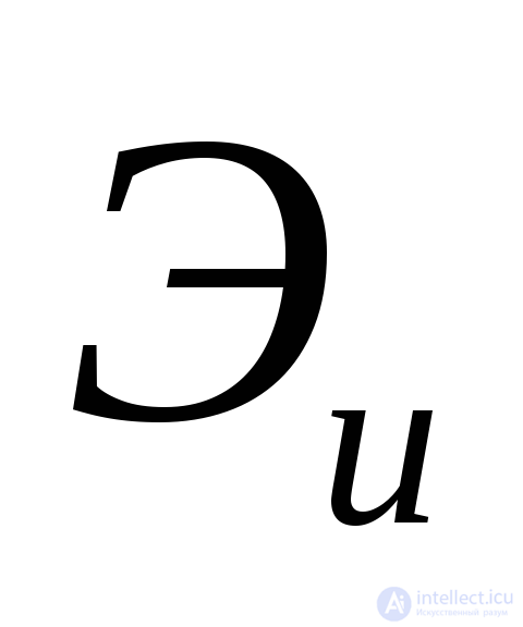 is the energy of the radiated signal;
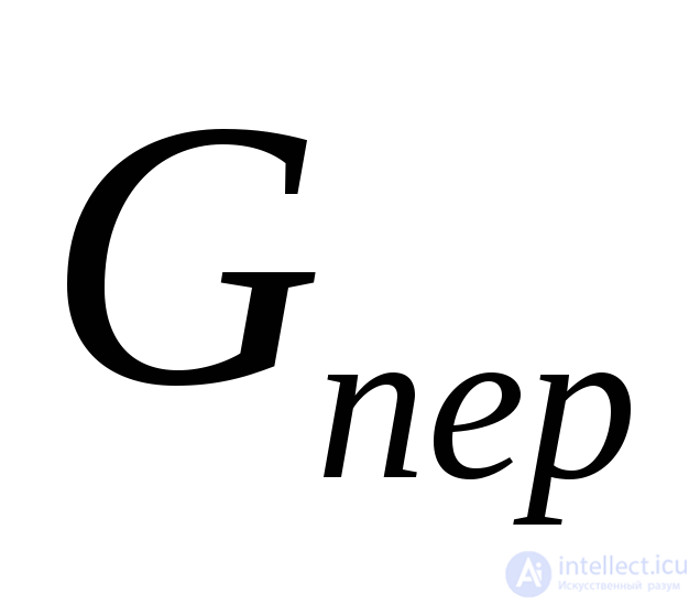 is the gain of the transmitting antenna;
 is the effective area of the receiving antenna;
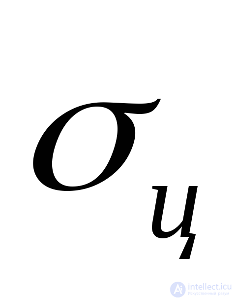 is the radar cross section (RCS) of the target;
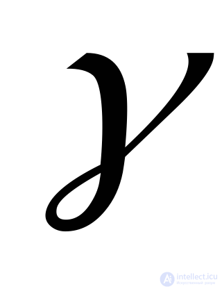 is the discrimination factor (the required signal-to-noise power ratio at the output of the optimal filter):
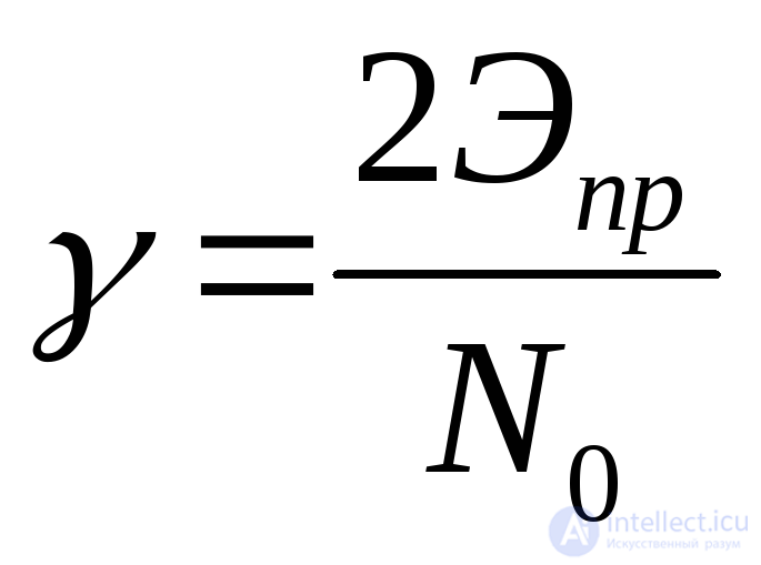 ,
,
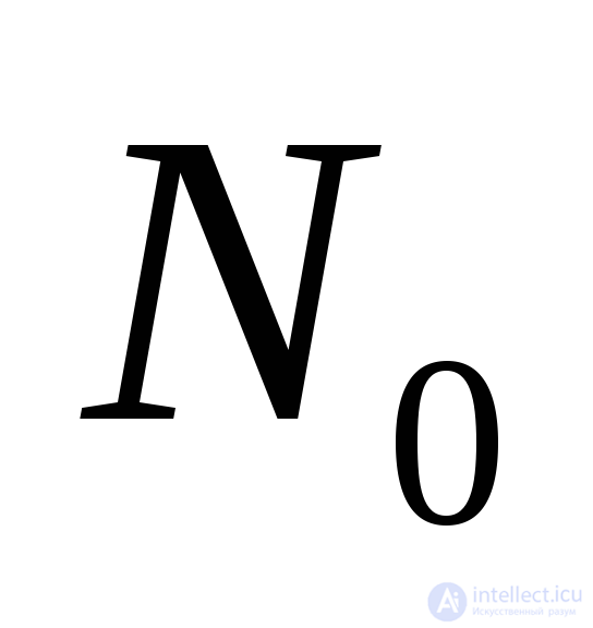 is the power spectral density of the receiver's intrinsic noise, referred to its input;
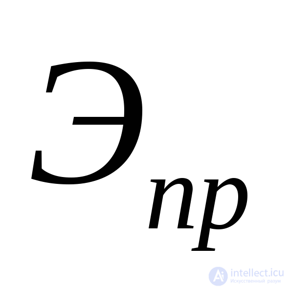 is the energy of the received signal when a target is detected at maximum range with the specified quality indicators.
The quantity 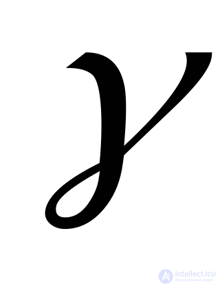 is also called the detection parameter. It is determined from detection curves based on the specified values of the detection quality indicators — the probability of detection D and the probability of false alarm F.
Let us find out how the probing signal parameters affect the radar range.
The energy of the radiated signal is determined by the expression
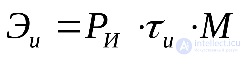 ,
,
where  is the number of pulses in the burst with which the target is illuminated during its dwell within the main lobe of the radar antenna pattern.
The last expression shows that, to increase the radar range, it is necessary to increase:
the transmitter peak pulse power  ;
;
the probing signal duration 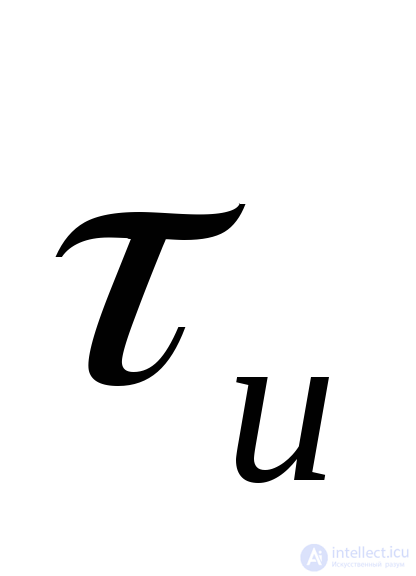 ;
;
the number of pulses in the burst  .
.
However, the possibilities for increasing these parameters are limited. Increasing the peak pulse power  is accompanied by stricter requirements on the electrical strength of the path carrying electromagnetic energy from the transmitter to the antenna, and also reduces the radar's stealth (low probability of intercept) and its protection against homing weapons.
Increasing the probing pulse duration (if it is a simple radio pulse) reduces the range resolution and the radar's protection against passive interference (clutter).
To increase the number of pulses  in the burst, one must either raise the repetition frequency
 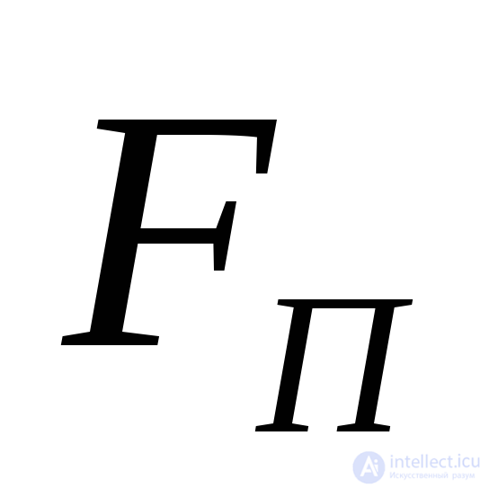 of the probing signals, which entails a reduction of the unambiguous range measurement:
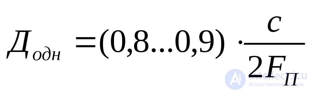 ,
,
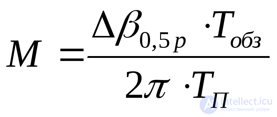
or reduce the azimuth scan rate, or increase the beamwidth of the antenna pattern in the horizontal plane, since
 ,
,
where 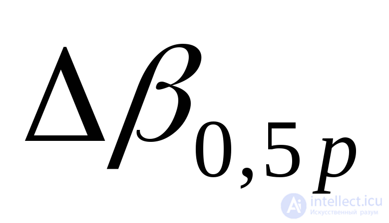 is the antenna pattern width in radians;
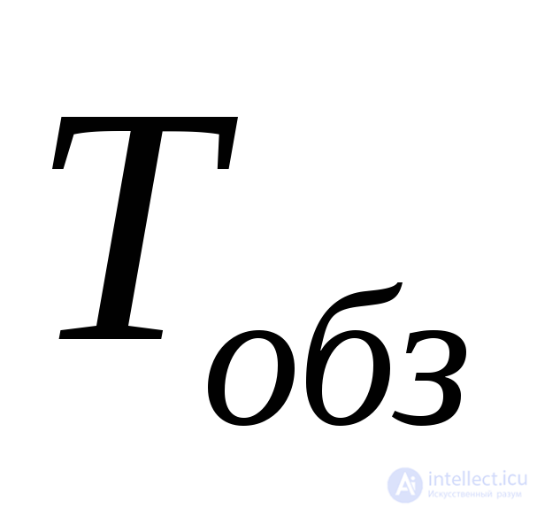 is the scan period (the time of one antenna revolution).
Note that increasing the antenna beamwidth degrades the radar's protection against passive and active interference and worsens the azimuth resolution.
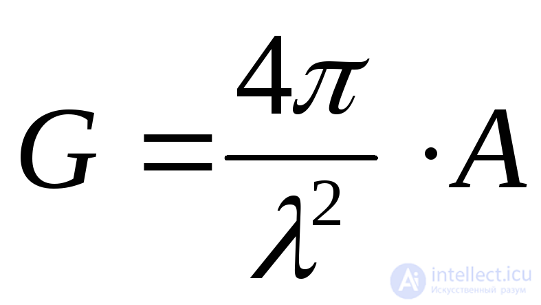
When assessing the influence of wavelength on radar range, one must take into account that in radar the same antenna is, as a rule, used for both transmission and reception. In this case the effective area  and the gain
 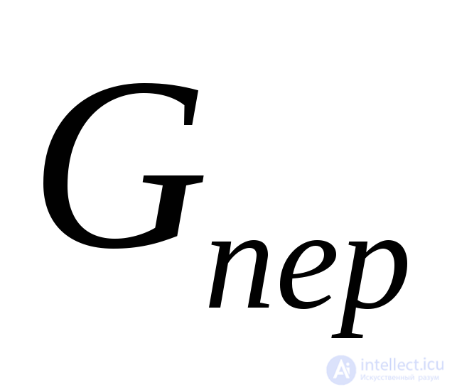 of the antenna are related by:
 .
.
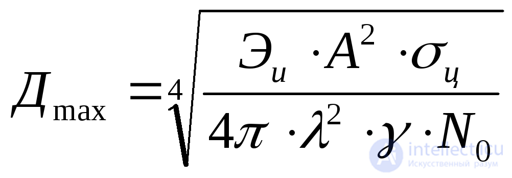
Therefore, expression (3.3) can be rewritten as follows:
 (3.4)
(3.4)
It follows directly from formula (3.4) that, for  , increasing the wavelength reduces the range. However, when the wavelength changes, the other quantities in formula (3.4) do not remain constant. For example, the mean target RCS
 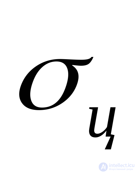 depends on wavelength. In the meter-wave band it is larger than in the decimeter band, and even more so than in the centimeter band, so increasing the wavelength increases the radar range. In addition, as the wavelength increases, reflections from the underlying surface also increase the radar range at medium and high altitudes, but reduce the detection range of targets at low altitudes.
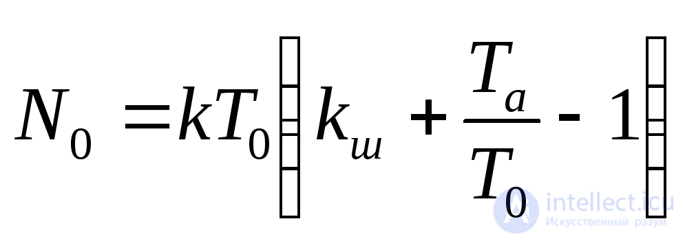
The noise power spectral density 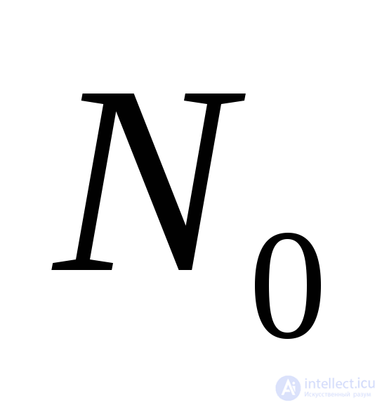 in the radio band is determined by the relation
 ,
,
where  is the Boltzmann constant;
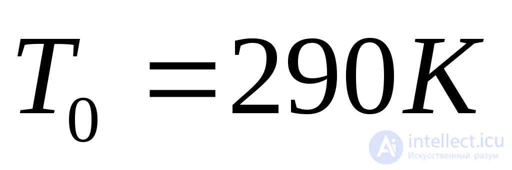 is the absolute temperature of the receiver (in kelvins);
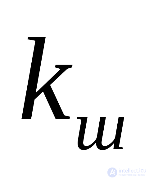 is the intrinsic noise figure of the receiver;
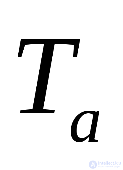 is the antenna noise temperature, which accounts for the reception of interfering emissions depending on the wavelength, the shape of the antenna pattern, and its orientation.
The ratio 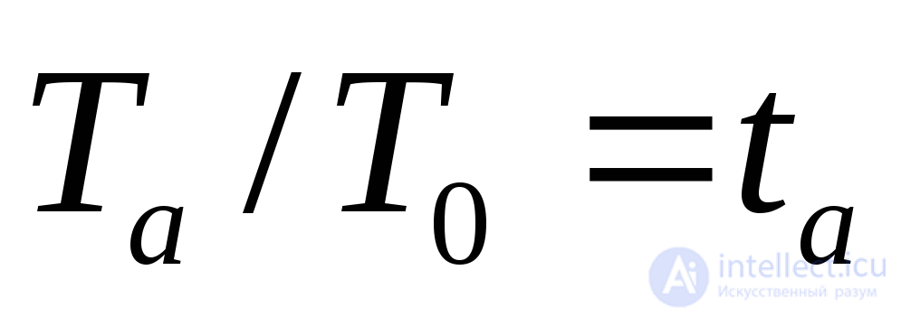 is called the relative effective noise temperature of the antenna.
In the meter-wave band (for ) the quantity
 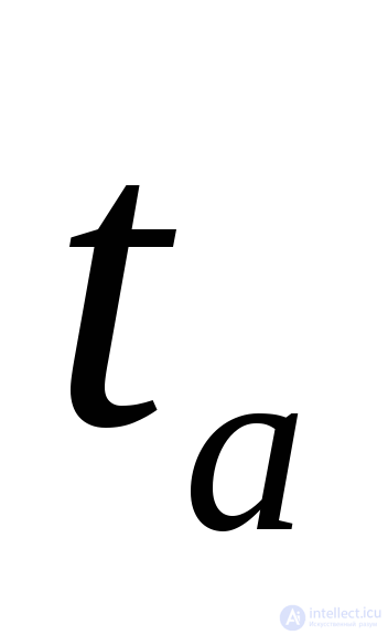 is calculated using the empirical formula:
 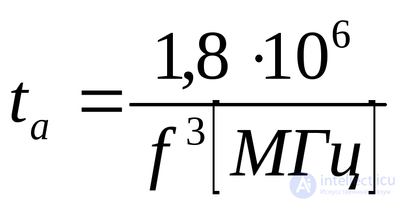 . For example, for
 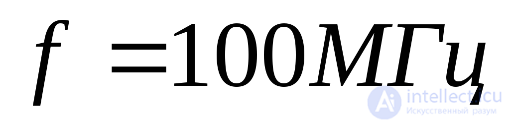 ,
,  . The intrinsic noise figure of low-noise receivers is
 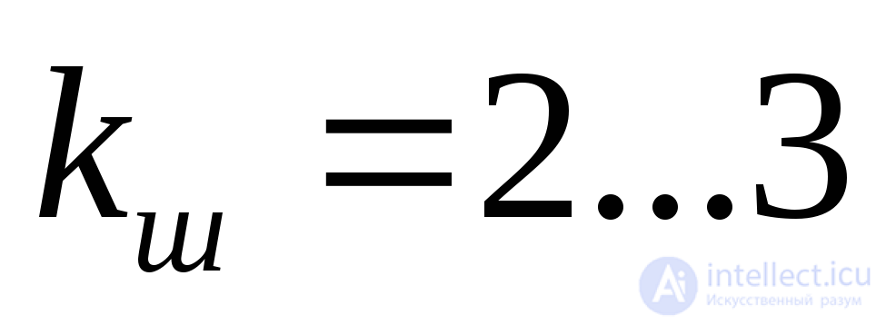 .
.
Consequently, in the meter-wave band the noise of external sources must be taken into account, since 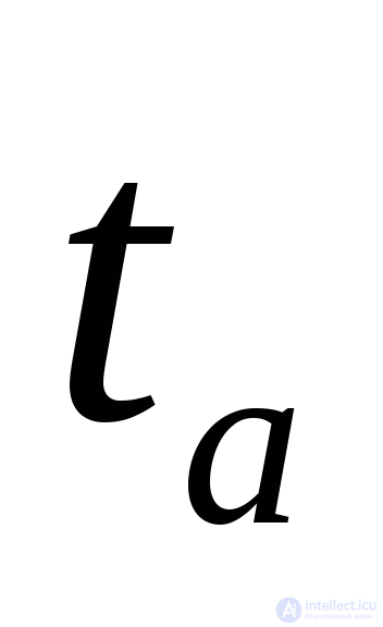 depends significantly on frequency, and hence so does the noise power spectral density. The higher the radar operating frequency (the shorter the wavelength), the smaller the influence of external noise. In the decimeter and centimeter bands the influence of external noise can be neglected.
Attenuation of radio waves in the troposphere, caused by scattering and absorption of electromagnetic energy in the troposphere, has a noticeable effect on radar range. Thus, the radar range with attenuation taken into account is determined by the expression
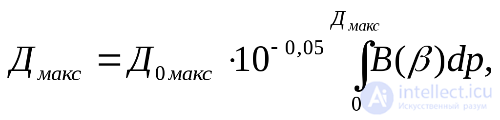 (3.5)
(3.5)
where 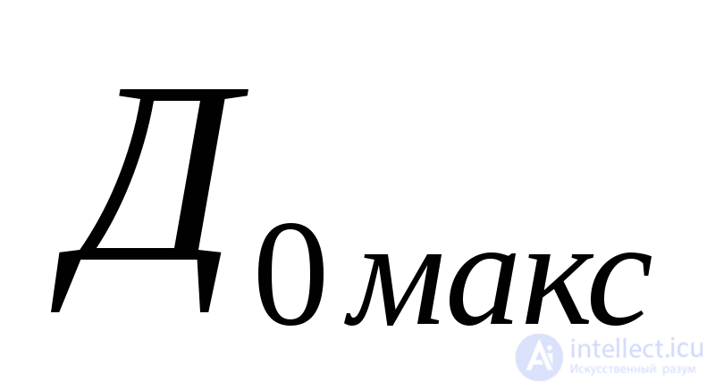 and
and 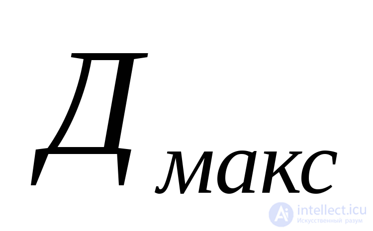 are the maximum radar range without and with radio wave attenuation, respectively;
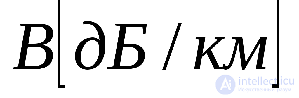 is the attenuation coefficient.
Equation (3.5) is transcendental and can be solved graphically, for example by finding the intersection point of the functions 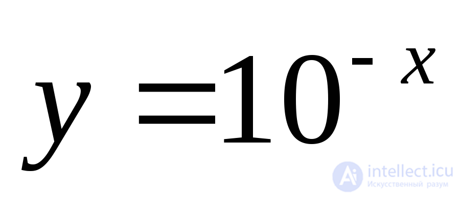 and
and 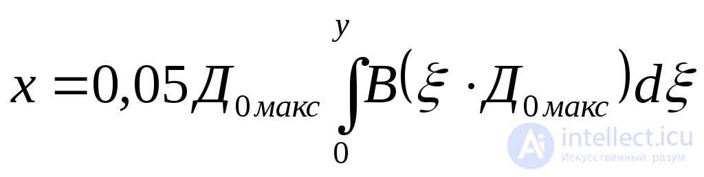 ,
,
where 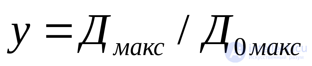 .
.
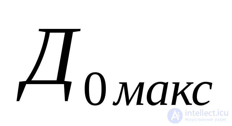
Fig. 3.21 shows the solution curves of equation (3.5) for a homogeneous path, as the dependence of the radar range in the atmosphere in kilometers 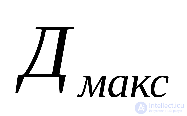 (ordinate axis) on the radar range in free space
  (abscissa axis) for various values of the attenuation coefficient
  .
.
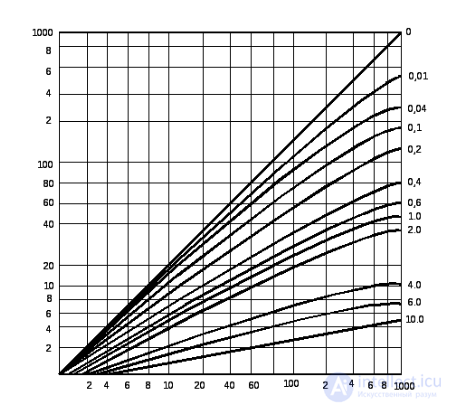
Fig. 3.21. Dependence of radar range in a homogeneous atmosphere on the free-space range for various values of the attenuation coefficient  .
.
The value of the attenuation coefficient  can be estimated from the graphs in Fig. 3.22 and 3.23. Fig. 3.22 shows that at wavelengths close to one centimeter there are resonant absorption maxima of electromagnetic energy. This is determined by features of the molecular structure: 1.35 cm, 1.5 mm, and 0.75 mm in water vapor, and 0.5 cm and 0.25 cm in oxygen. It is precisely the dipole molecules of oxygen and water vapor, as well as particles of condensed moisture and dust, that cause the attenuation of radio waves in the troposphere.
Attenuation of radio waves in the ionosphere arises from the oscillatory motion of free electrons under the influence of electromagnetic energy. Most of the oscillation energy is re-radiated, but part of it, owing to collisions, is converted into the kinetic energy of the random motion of atoms and ions. The attenuation is significant if both the concentration of free electrons and the concentration of neutral atoms and ions are high at the same time. Numerically, the attenuation  in decibels per kilometer is approximately expressed by the relation
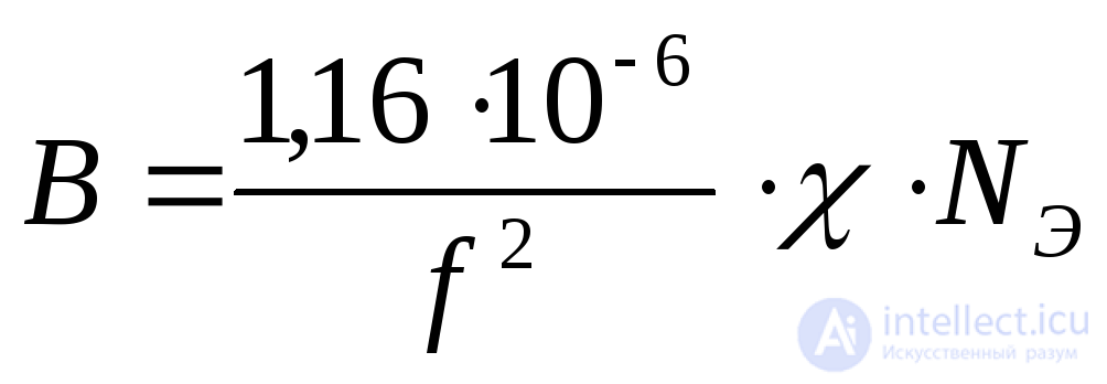 ,
,
where 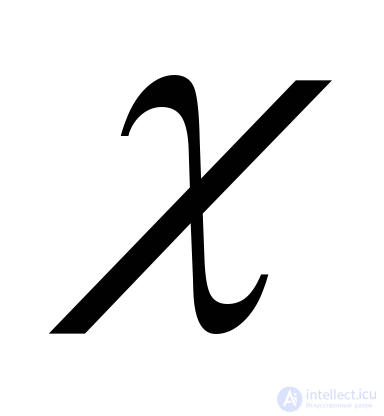 is the effective collision frequency of electrons with neutral atoms or ions (Hz);
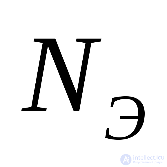 is the electron concentration (
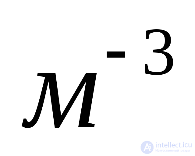 )
)
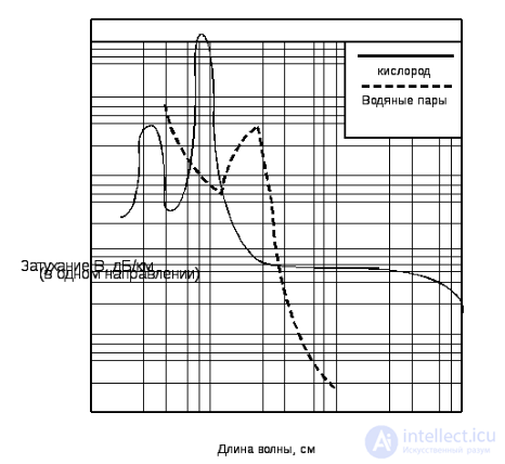
Fig. 3.22. Dependence of the attenuation coefficient  on wavelength for oxygen (solid line) and water vapor (dashed line).
An idea of the possible order of magnitude of 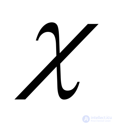 in the ionosphere can be obtained from the table
|
Altitude, km. |
65 - 70 |
80 |
95 |
120 |
300 |
|
|
|
|
|
|
|
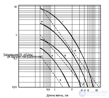
Fig. 3.23. Dependence of the attenuation coefficient  on wavelength for rain and fog.
The solid curves show the attenuation due to rain of intensity: a — 0.25 mm/h (drizzle); b — 1 mm/h (light); c — 4 mm/h (moderate); d — 16 mm/h (heavy).
The dashed lines show the attenuation in fog or clouds: e — 0.032 g/m³ (visibility 600 m); f — 0.32 g/m³ (visibility 130 m); g — 2.3 g/m³ (visibility 30 m).
From Fig. 3.22 and 3.23 it follows that, excluding the case of backscatter-oblique sounding, in the radar frequency band the attenuation in the ionosphere is negligibly small (fractions of a dB). For long-range surveillance radars it is inadvisable to use wavelengths shorter than 10 cm. The greater the required radar range, the longer the wavelength must be, from the standpoint of ensuring acceptable attenuation of electromagnetic energy along the propagation path.
It follows from the above discussion that the dependence of radar range on the wavelength of the radio pulse is complex and ambiguous.
The accuracy of target coordinate measurement is one of the most important characteristics of a radar, determining its capabilities in target designation for the active branches of the air defense forces and air force and in fighter guidance.
The measurement error is the difference between the true and measured values of the parameter 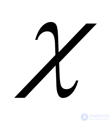 :
: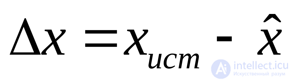 ,
,
where 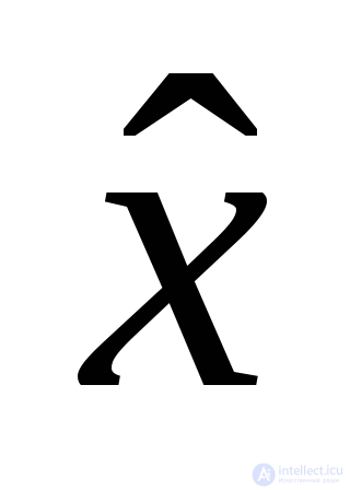 is the measured value (estimate) of the parameter.
Measurement errors are divided into gross errors (blunders), systematic errors, and random errors. Gross and systematic errors can in principle be eliminated. Random errors can be minimized but cannot be completely eliminated. They are caused by interference at the receiver input, its intrinsic noise, signal fluctuations, and imperfections and instabilities in the elements and devices of the radar.
The quality indicators of target coordinate measurement accuracy most widely used in practice are:
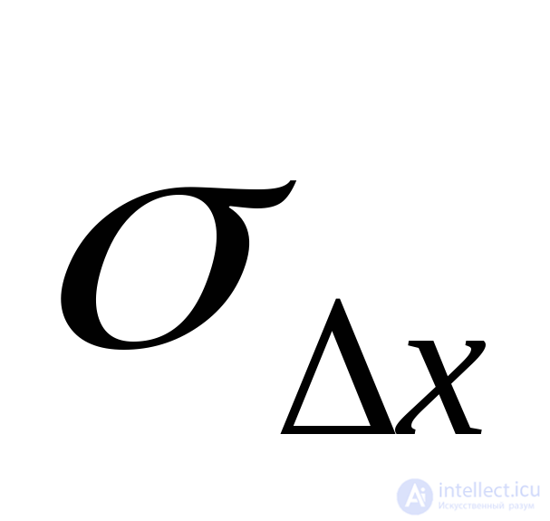 ;
;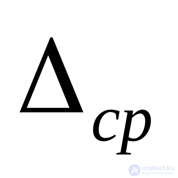 ;
;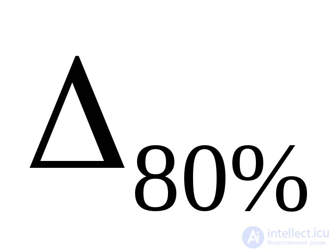 ;
;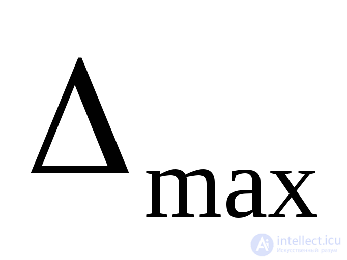 .
.For an arbitrary probability density distribution law 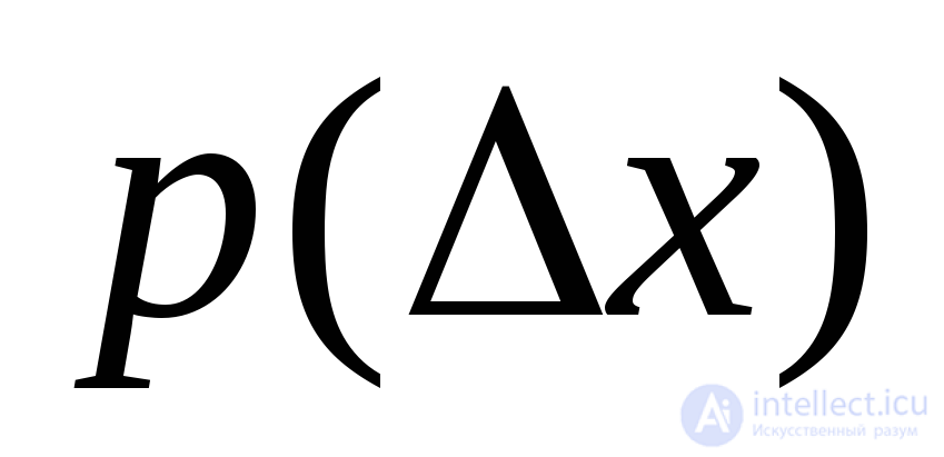 , the RMS error is determined from the relation
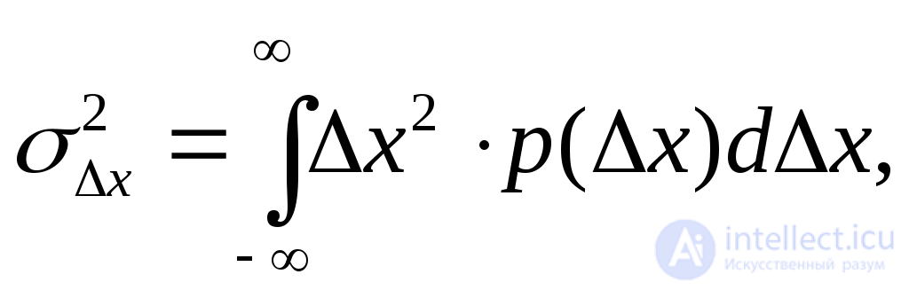 for
for 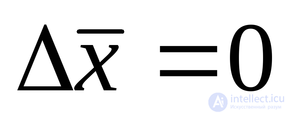 (3.6)
(3.6)
The condition 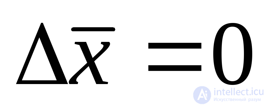 means that there is no systematic error; owing to the influence of many factors, the error distribution law is usually assumed to be normal
  .
.
In this case the RMS error fully characterizes the other types of errors. The probability that the error 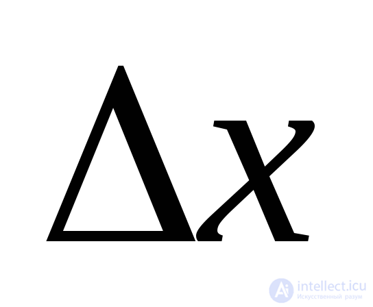 does not exceed the value
 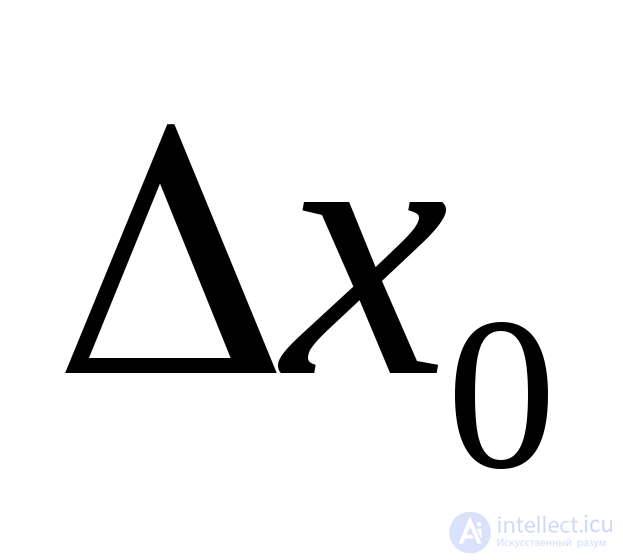 is equal to
 ,
,
where  is the Gaussian error integral;
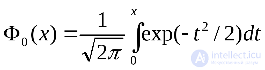 is a tabulated function (for example, I.N. Bronshtein, K.A. Semendyaev, "Handbook of Mathematics for Engineers and University Students," Table 1.1.2.6.2).
The numerical value of the probability is equal, for:
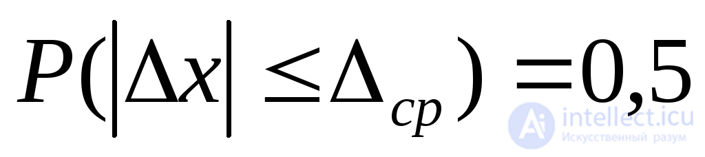 ;
;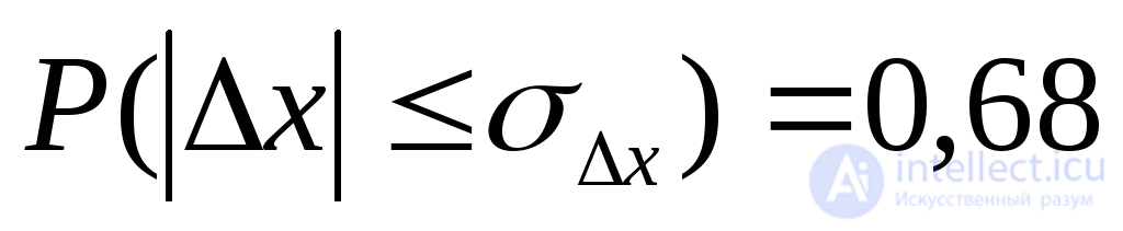 ;
;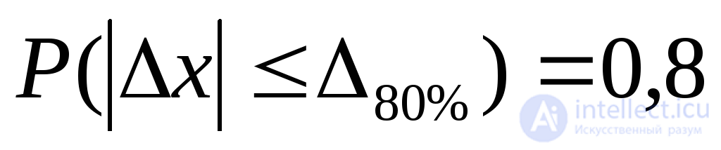 ;
; ;
;It can be shown that the relationship between the errors is given by the following relations: 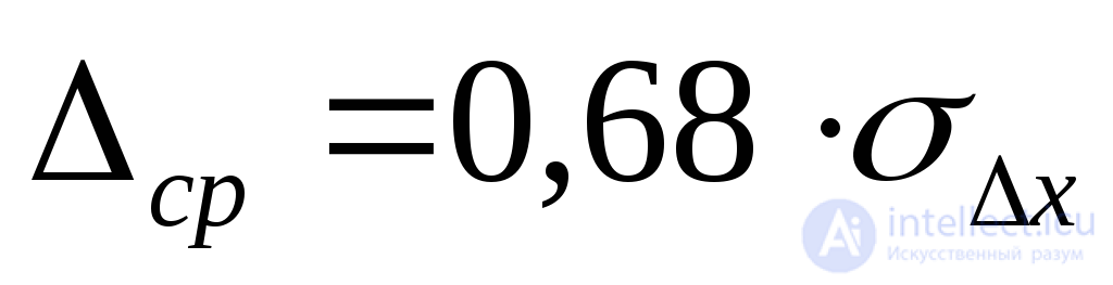 ;
; 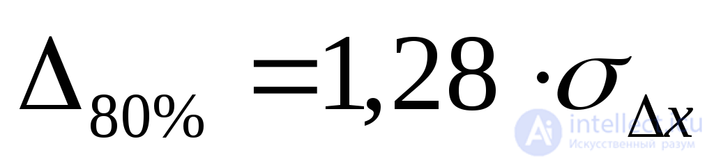 ;
; 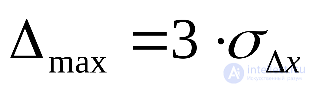 .
.
In digital processing, radar signals are sampled in time and quantized in amplitude, which leads to additional coordinate measurement errors. The distribution law of the sampling (quantization) errors is uniform, i.e., the probability density of the error is  , where
 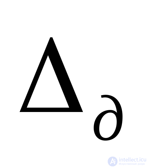 is the step or sampling interval.
In accordance with (3.6), the RMS sampling error is
 .
.
Hence
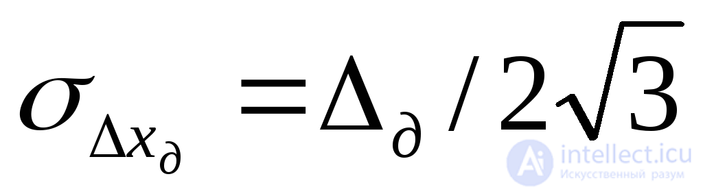 . (3.7)
In the general case, the RMS error of measuring an independent coordinate (range, azimuth, or elevation) is determined by the relation:
 , (3.8)
where 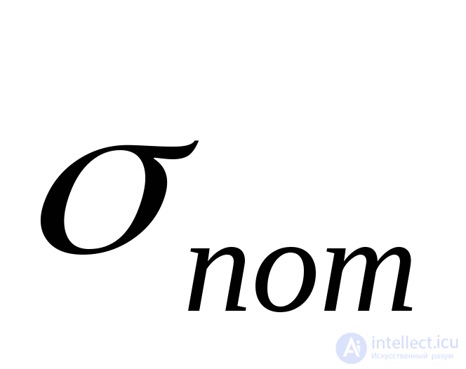 is the potential (theoretical) coordinate measurement error;
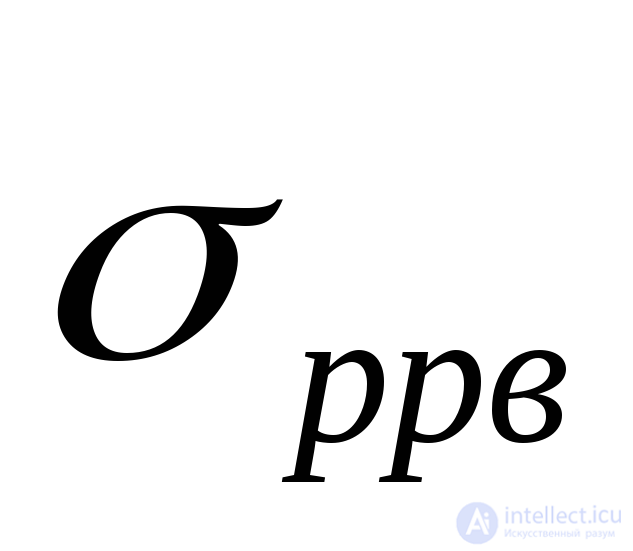 is the error caused by the peculiarities of radio wave propagation in the atmosphere;
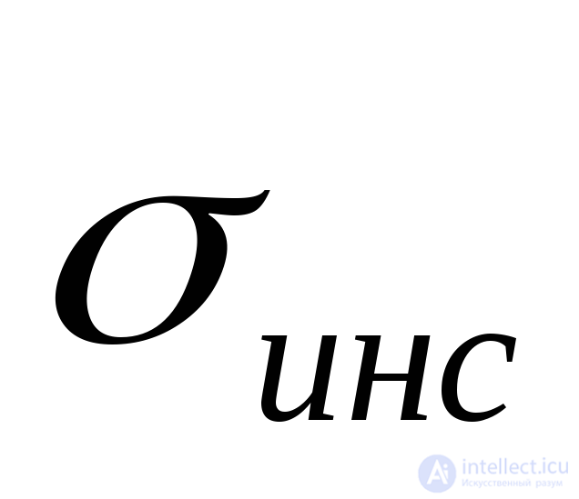 is the instrumental error caused by the non-ideal operation of radar elements and units, as well as by the measurement method;
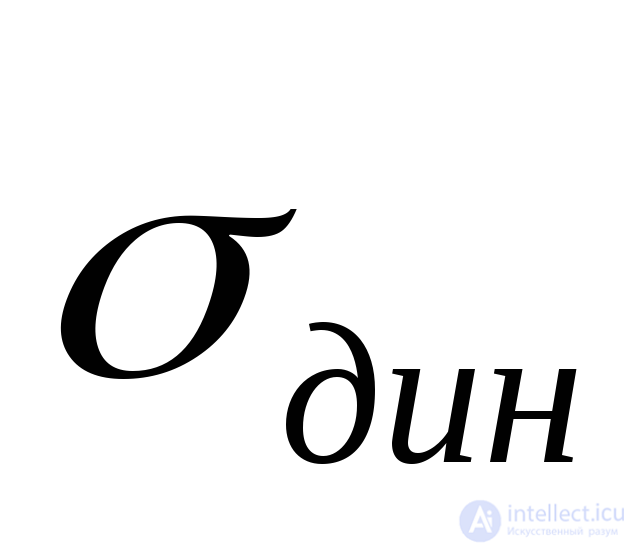 is the dynamic error caused by the change in target position during the measurement time.
The potential measurement error characterizes the ultimate achievable accuracy and is determined by the signal-to-noise ratio and the spectrum width of the probing signal
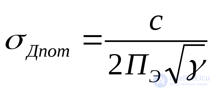 ,
,
where 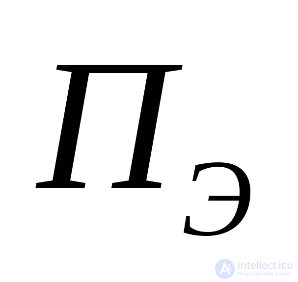 is the effective spectrum width of the probing signal; (for a radio pulse with a bell-shaped envelope
 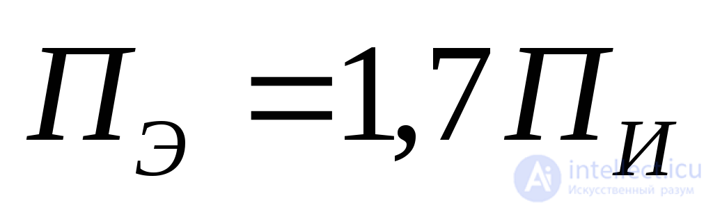 .
. 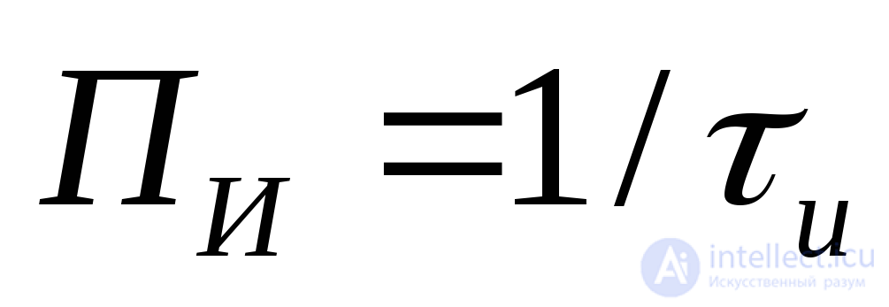 is the signal spectrum width at the 0.46 level);
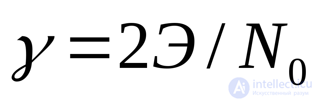 is the signal-to-noise ratio at the output of the optimal filter (or at the input of the measuring device)
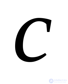 is the speed of light.
To improve the potential accuracy of range measurement to a target, it is necessary, as in increasing the radar range, to increase the energy of the received signal and reduce the noise power spectral density of the receiver.
In addition, to improve the potential accuracy of range measurement to a target (to reduce 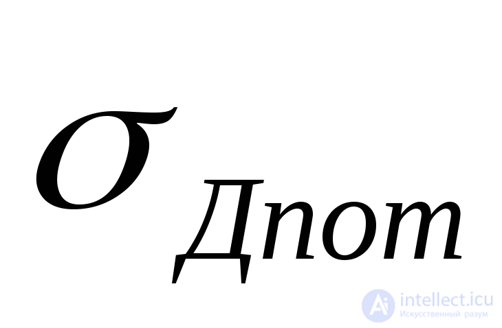 ), it is necessary to increase the spectrum width of the probing signal, which in the case of simple radio pulses requires shortening them and therefore reduces the signal energy. Thus, a contradiction arises when simple radio pulses are used, and it can be resolved by using complex-modulated signals.
In practice, the potential range measurement error in surveillance radars, even with relatively narrowband signals, does not, as a rule, exceed 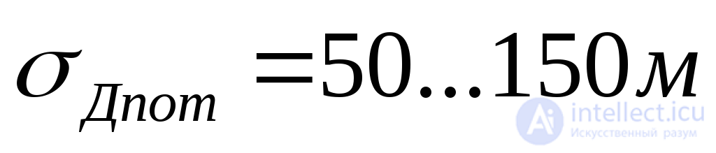 and amounts to an insignificant part (10…15%) of the total range measurement error with visual readout of information. With automatic measurement of target coordinates, * can make a significant contribution to the total measurement error.
The other components of the range measurement error in expression (3.8) do not depend directly on the structure of the probing signal and are therefore not considered in detail in this chapter.
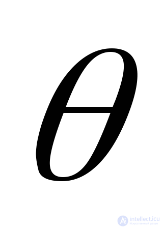
The potential angular coordinate measurement error is determined by the shape and width of the antenna radiation pattern in the corresponding plane, the signal-to-noise ratio at the input of the measuring device, and the coordinate measurement method. In the general case
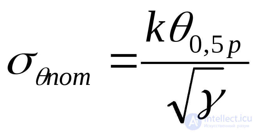 ,
,
where 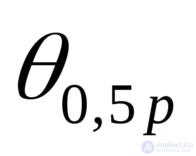 is the antenna beamwidth in the corresponding plane;
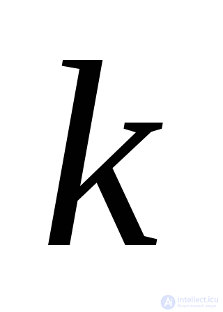 is a proportionality coefficient that depends on the shape of the radiation pattern and on the method used to measure the angular coordinate
  .
.
The numerical value of the coefficient 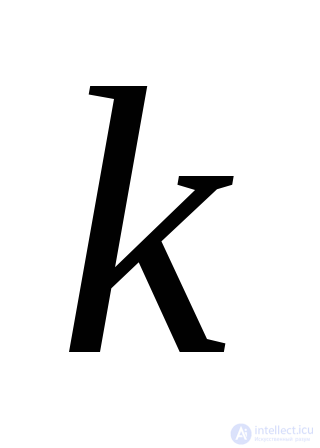 is:
is: 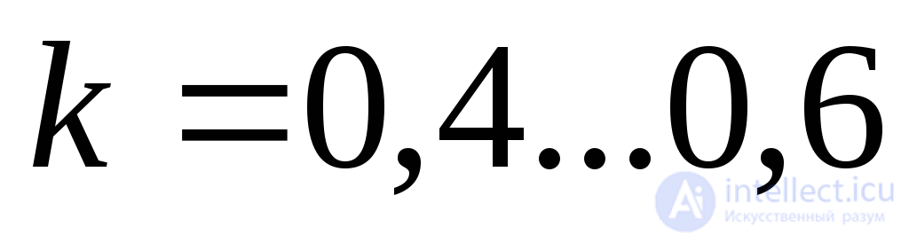 when the angular position of a target is measured by linear scanning of the radiation pattern beam (used to measure target azimuth in surveillance radars and elevation angle in radio altimeters);
 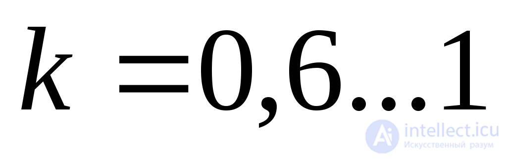 when
when 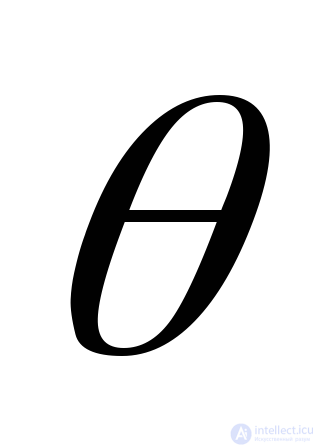 is measured by the partial-pattern (multi-beam) method (in three-coordinate radars).
In metre-wave radars, the potential azimuth measurement error at the edge of the detection zone, caused by the wide radiation pattern in the azimuth plane, can be significant. For example, for 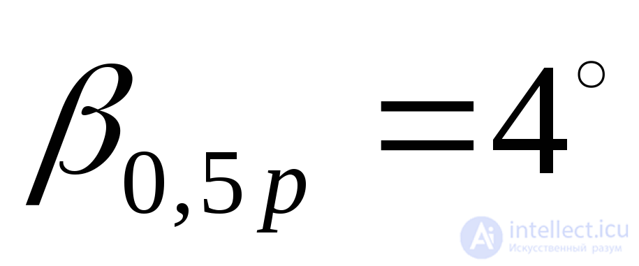 at the edge of the detection zone
 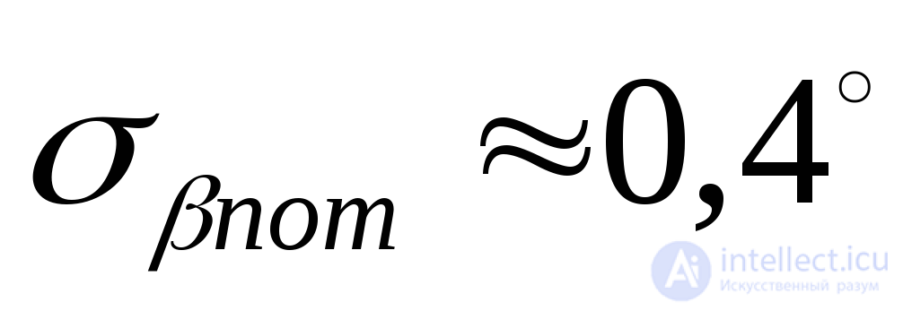 .
.
To improve the accuracy of angular coordinate measurement (to reduce 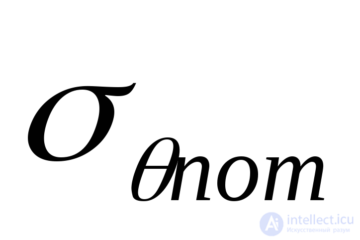 ), it is necessary, as in the case of range measurement, to increase the signal-to-noise ratio
 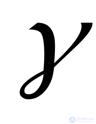 at the output of the optimal filter and, in addition, to narrow the radiation pattern. For a fixed antenna size, this is achieved by reducing the wavelength
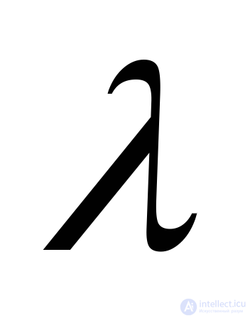 .
.
The remaining components of the target angular coordinate measurement error (see expression (3.8)) do not depend directly on the parameters of the probing signal.
The coordinate resolution of a radar determines the completeness of the information on the air situation when there are many targets (point and distributed) in the radar coverage area. It also affects the radar's ability to reveal the group composition of targets, as well as its immunity to passive interference.
The resolution of a radar in a given coordinate is understood as the minimum difference in that coordinate between two targets, with all their other coordinates coinciding, at which the targets are observed separately.
In the general case this definition is not rigorous, since the quality criteria of resolution are not specified. In real conditions, when the processes of radar detection and resolution are accompanied by interfering noise, one must speak of statistical resolution, that is, resolution of targets with a given probability or with an acceptable degradation of detection quality.
A distinction is made between potential and actual resolution.
Potential resolution characterizes the ultimate achievable resolution and is determined by the signal-to-noise ratio and by the extent of the cross-section of the ambiguity function (the two-dimensional autocorrelation function) of the radar probing signal along the resolution parameter. The higher the signal-to-noise ratio and the smaller the extent of the ambiguity function along the corresponding parameter, the higher the potential resolution of the radar, all other things being equal.
Actual resolution is always worse than potential resolution. The factors that degrade resolution include:
Next, we consider the dependence of the potential radar resolution on the parameters of the probing signals by analyzing the corresponding two-dimensional autocorrelation functions.
The known schemes of optimal (matched) processing of radar signals are based on computing the correlation integral (its modulus)
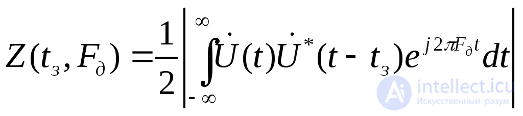 (3.9)
(3.9)
here 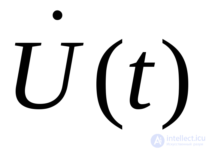 is the complex amplitude of the probing signal;
 is the complex amplitude of the expected signal, taking into account the delay
 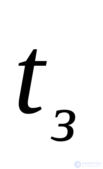 and the Doppler frequency shift
 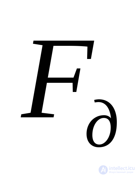 ; the minus sign in the exponent accounts for the fact that, at radial velocity
 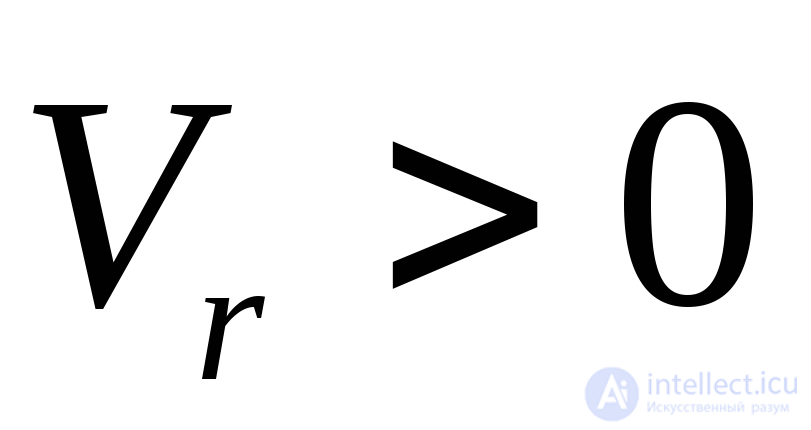 (a receding target), the frequency of the reflected signal is lower than that of the probing signal.
The received signal 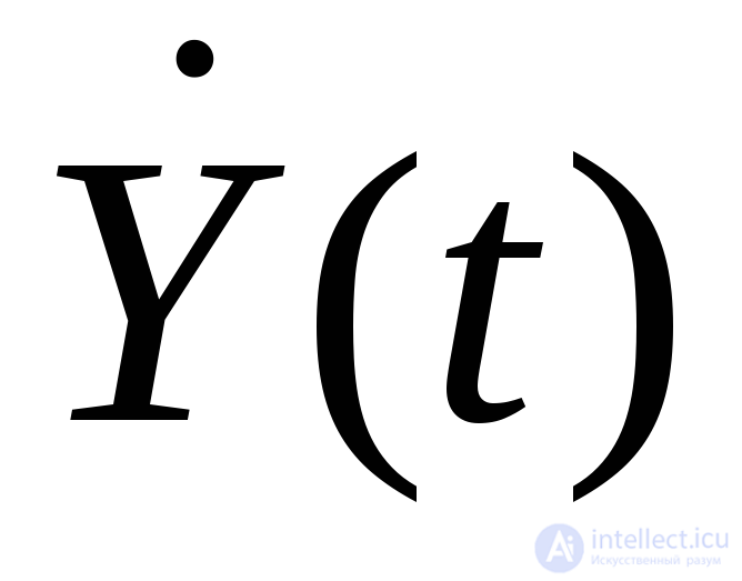 is, in the general case, the sum of the complex amplitudes of the signal and the interference:
 , (3.10)
where 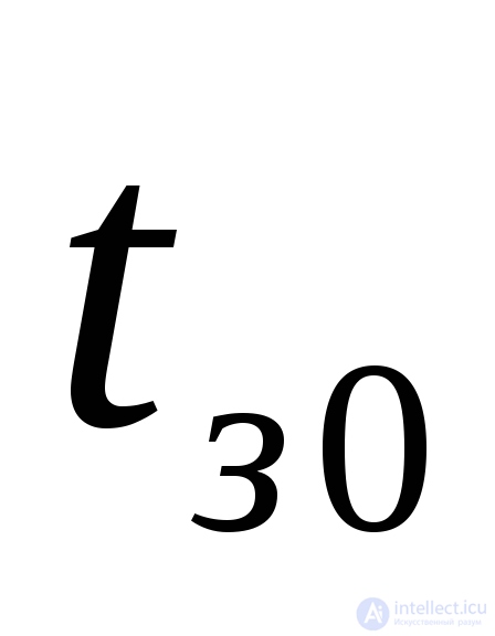 and
and 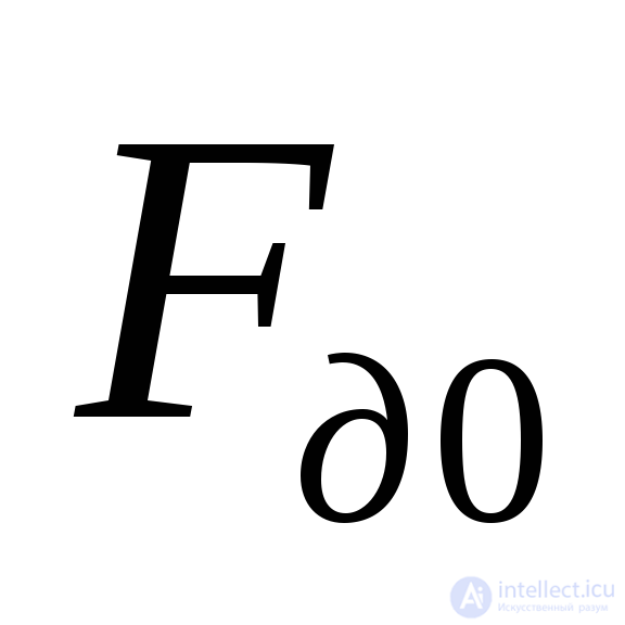 are the true values of the delay and Doppler frequency of the useful signal. Taking (3.10) into account, the modulus (3.9) reduces to the modulus of the sum of two complex quantities
 (3.11)
The first quantity 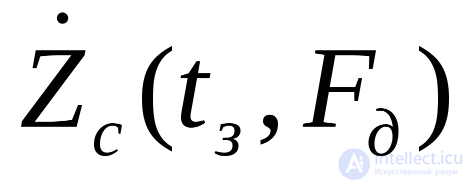 , for a non-random signal amplitude, is non-random and is expressed by an integral that depends on the signal:
 (3.12)
The second is a random quantity, which is smaller the weaker the interference, and is expressed by the integral:
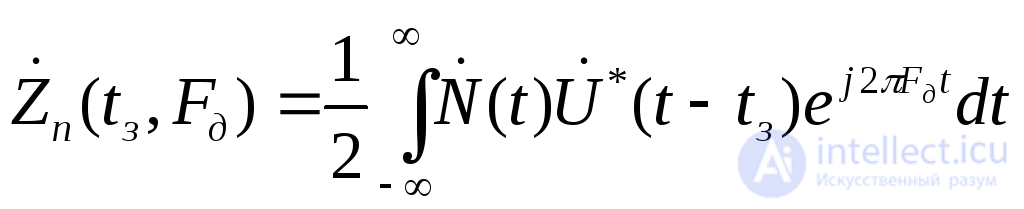 (3.13)
The signal integral (3.12) and its modulus are functions of the differences between the expected 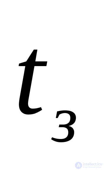 and true
 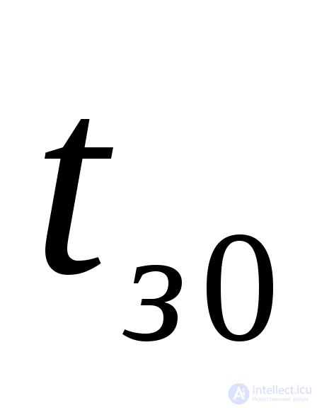 delay times, and between the expected
 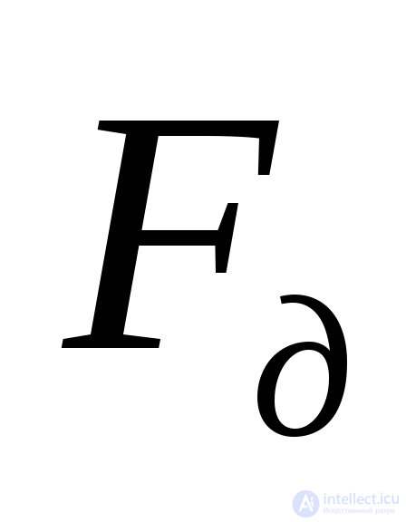 and true
 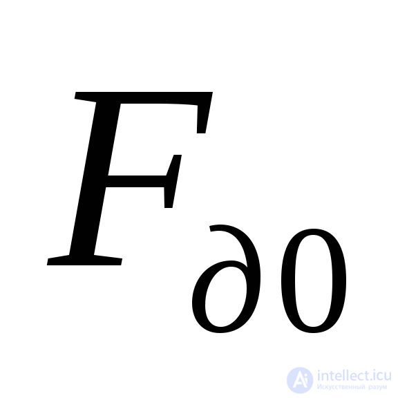 Doppler frequencies.
 (3.14)
where 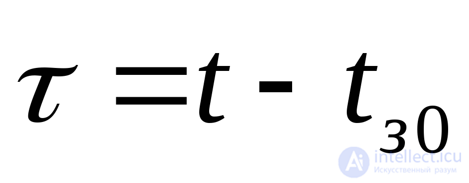 ,
, 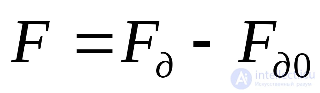 .
.
Let us calculate the function 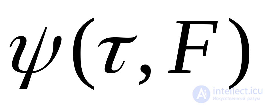 . To do this, we make the change of variable
 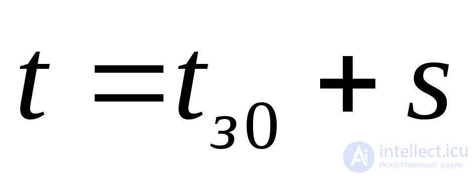 in integral (3.12) and take the factor
 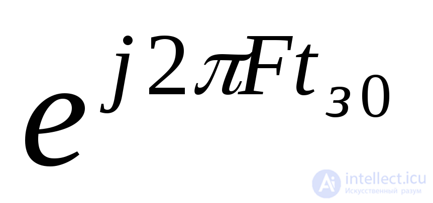 outside the integral sign. Replacing the modulus of a product with the product of the moduli, where
 ,
,
we obtain
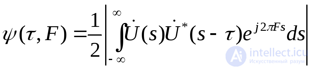 (3.15)
The function 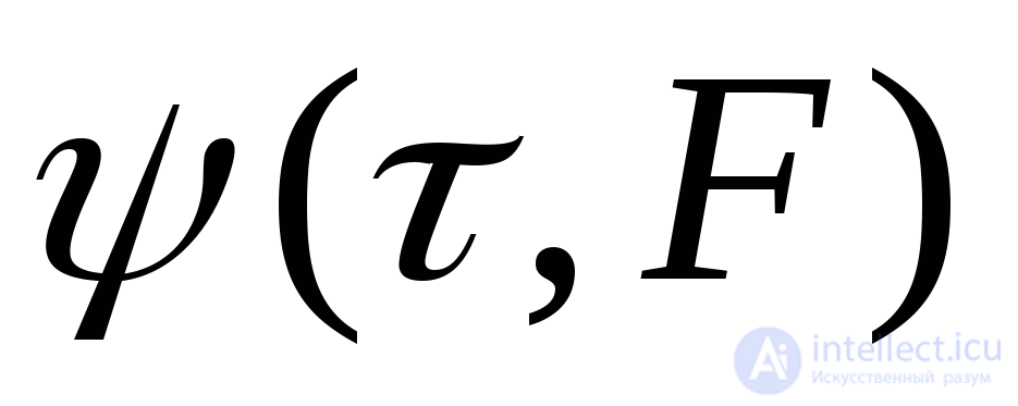 is called the two-dimensional autocorrelation function of the signal. It depends on its difference arguments
  ,
,  and does not depend on the values of
 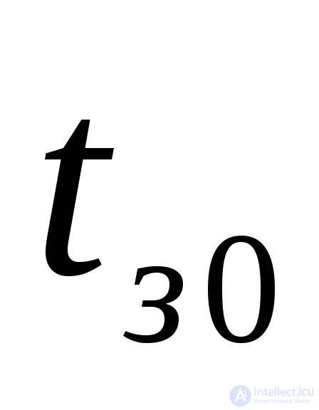 and
and 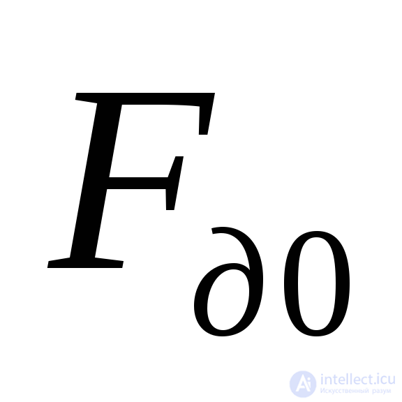 . In addition, the function
 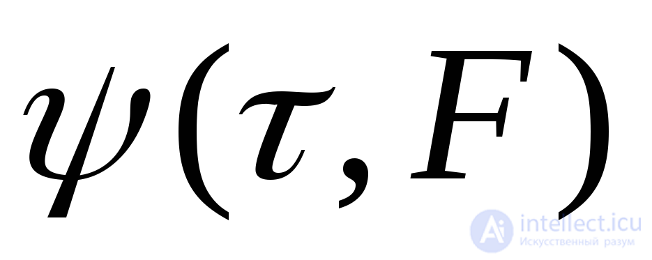 depends on the form of the complex envelope of the coherent signal
 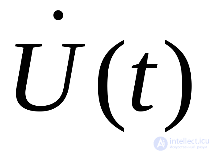 .
.
Like antenna radiation patterns, signal autocorrelation functions can be normalized. Since
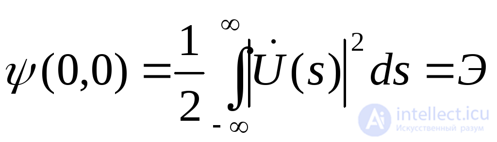 ,
,
where  is the signal energy, then
 (3.16)
The function 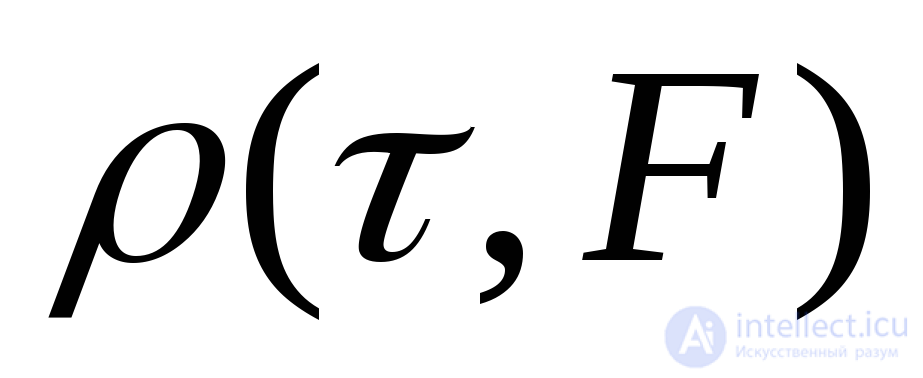 is called the normalized two-dimensional autocorrelation function of the signal.
An image of the two-dimensional autocorrelation function of the signal for a bell-shaped (Gaussian) radio pulse with constant instantaneous frequency is shown in Fig. 3.24.
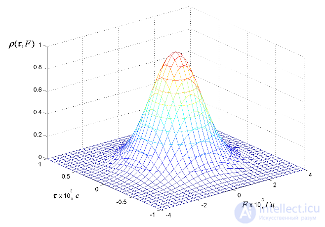
Fig. 3.24. Image of the two-dimensional autocorrelation function of the signal
Let us consider the properties of the autocorrelation function of the signal:
the property of central symmetry  ;
;
the value of 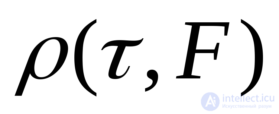 lies within the limits
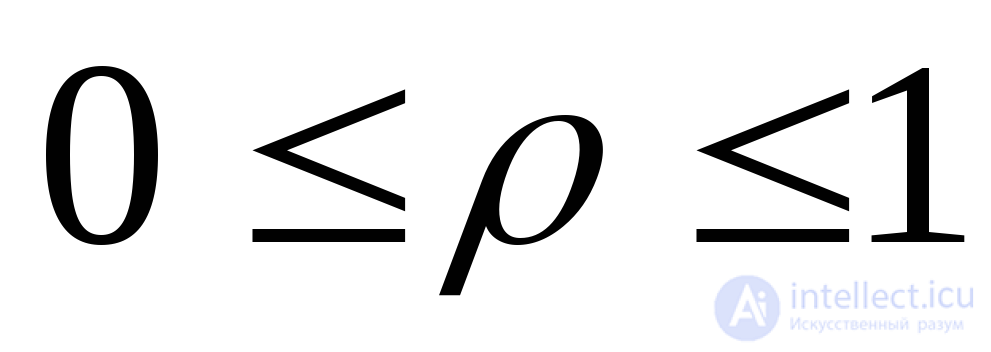 ,
, 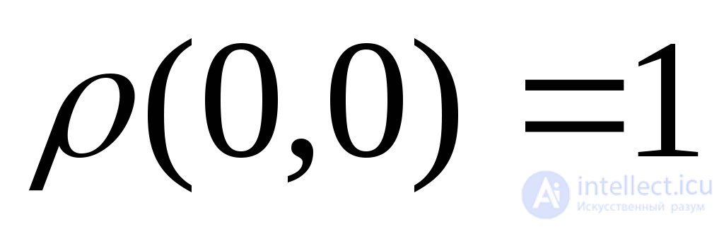 ;
;
each cross-section 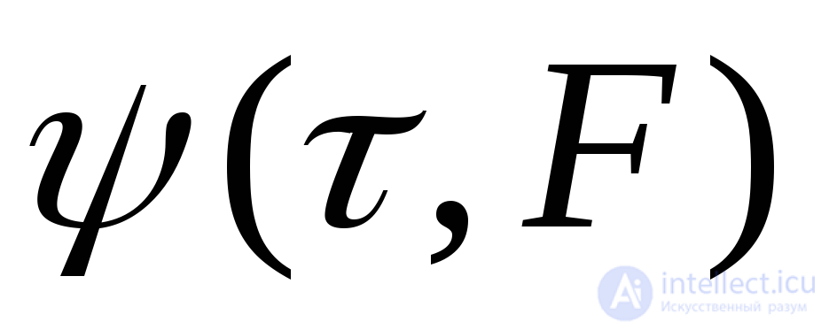 by a plane with fixed values of
  and
and  can be regarded as the output of the optimal processing correlation circuit or optimal filter when a noise-free signal is applied to it whose parameters (delay time and frequency) differ from the expected ones by
  and
and  , respectively.
By analogy with (3.16), we can write
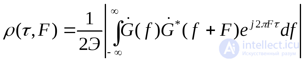 (3.17)
where 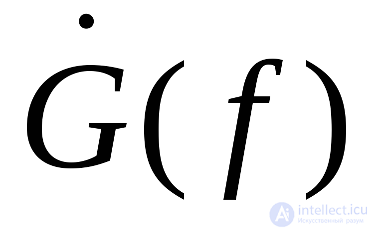 is the complex amplitude-frequency spectrum of the signal.
The cross-section 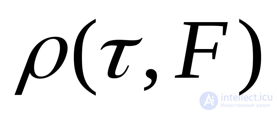 by the vertical plane
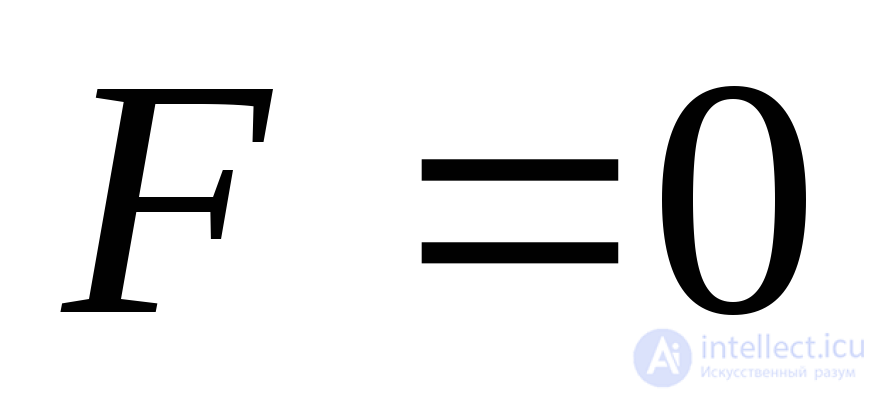 , as follows from (2.17), is described by the expression
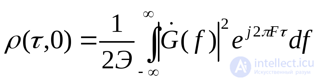 (3.18)
and is the Fourier transform of the squared amplitude spectrum of the signal. For a signal of limited spectral width  , this cross-section has the form of a pulse of duration
 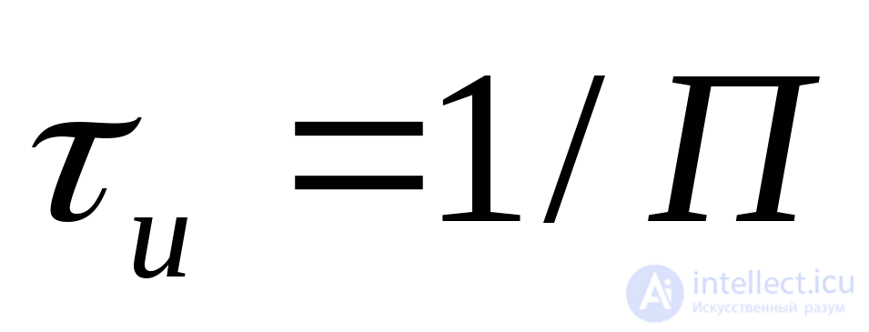 (Fig. 3.25), which in the literature is called the measure of resolution in delay time (in range).
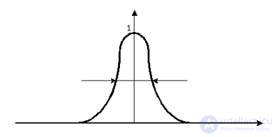
Fig. 3.25. Cross-section of the normalized two-dimensional autocorrelation function by the plane 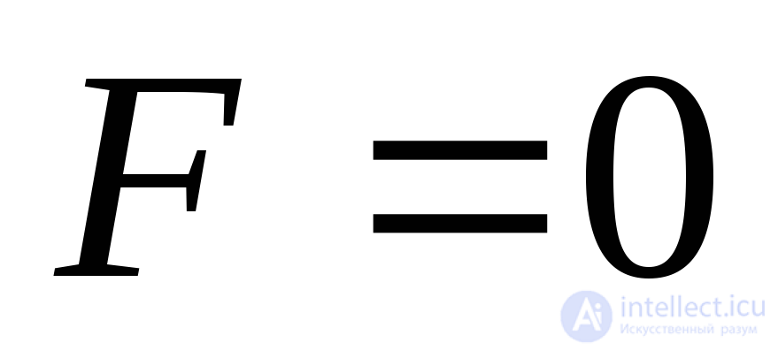
Let us consider the problem of resolving signals in time (in range) by analyzing the signals at the output of the optimal filter.
Suppose that rectangular pulses without intrapulse modulation, reflected from point secondary radiators, are processed optimally and are shifted in time by
 ,
,
where 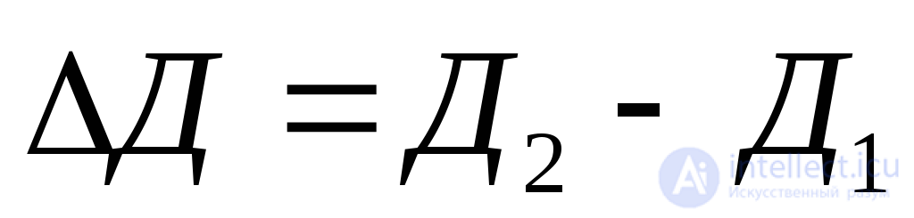 is the distance between the secondary radiators. Fig. 3.26 shows the envelopes of the optimal filter output pulses.
The value of the minimum interval 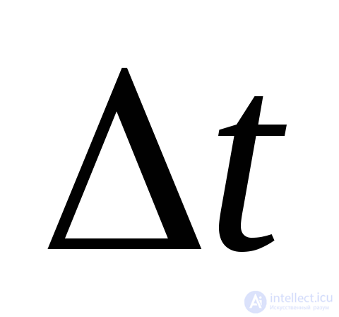 is determined by the possibility of observing adjacent pulses separately. In the case considered, the value
 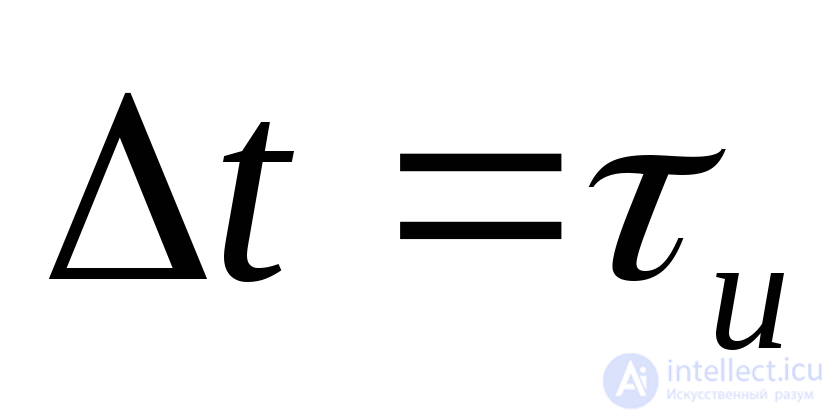 , at which the maximum of the envelope of the signal reflected from one target corresponds to the zero value of the pulse envelope from the other, can be taken as the conventional measure of resolution in time. Accordingly, the measure of range resolution is called
 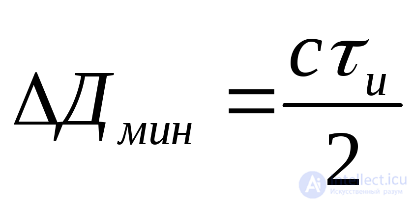 .
.
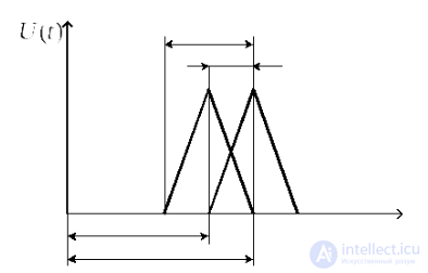
Fig. 3.26. Envelopes of reflected radio pulses from two targets closely spaced in range
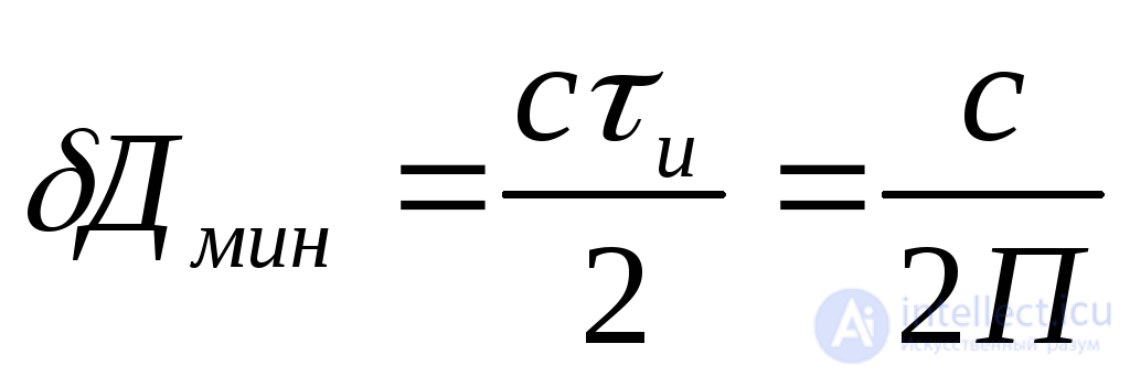
Thus, the potential range resolution of a radar is defined as
 (3.19)
and depends on the signal bandwidth.
The potential resolution in angular coordinates is determined by the half-power width of the antenna radiation pattern in the corresponding plane 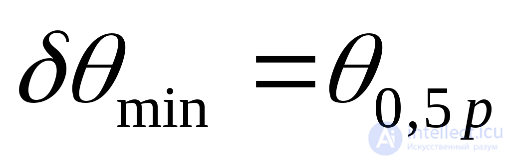 .
.
To increase the potential resolution, it is necessary, as in the measurement of angular coordinates, to increase the signal-to-noise ratio 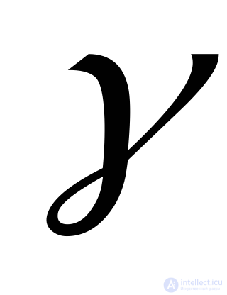 at the input of the measuring device (to raise the energy of the probing signal and, consequently, of the reflected signal), and also to reduce the angular dimensions of the antenna radiation pattern. The latter, for unchanged antenna dimensions, is achieved by reducing the wavelength
 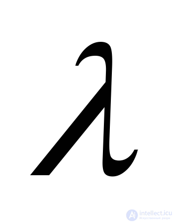 (raising the carrier frequency) of the probing signal.
A generalized measure of the range and angular resolution of a pulsed radar is the pulse volume, within which targets are not resolved.
The pulse volume is usually considered to be bounded by the half-power beamwidth of the antenna pattern 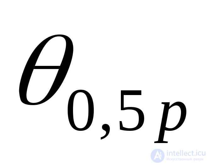 and by the length
 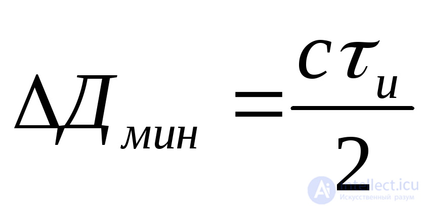 (Fig. 3.27), where
 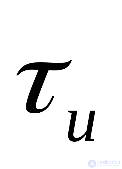 is the pulse duration at the output of the optimal processing circuit.
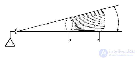
Fig. 3.27. Radar pulse volume
The wider the spectrum of the probing pulse (the smaller 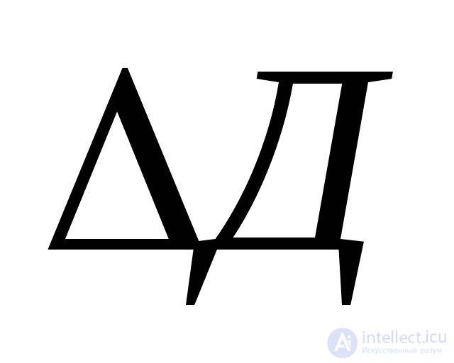 ) and the narrower the antenna beam (the smaller
 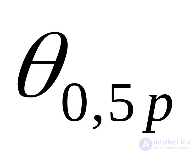 ), the smaller the pulse volume and the higher the resolution of the radar.
Targets can be resolved in velocity when a coherent burst of reflected signals is used, since it has a discrete spectrum (this problem will be considered in more detail below). Velocity resolution is frequency resolution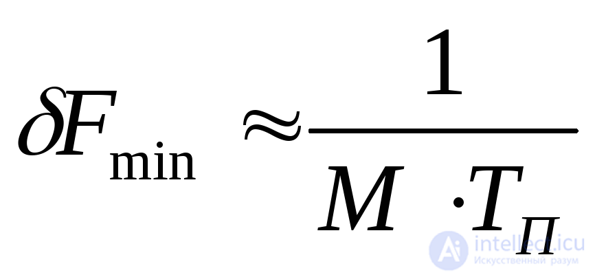 , where
  is the number of pulses in the burst and
 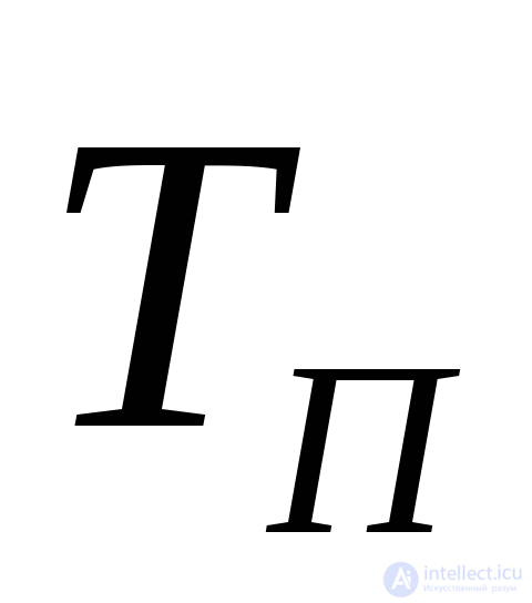 is the pulse repetition interval.
Velocity (frequency) resolution is higher the longer the duration of the pulse burst 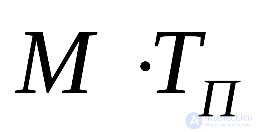 .
.
Radar jamming immunity is the ability of a radar to perform its specified functions under the influence of interference.
This characteristic is determined by the radar's covertness (low probability of intercept) and its noise immunity.
Radar covertness is understood as the probability that the enemy's electronic reconnaissance equipment will detect its operation and measure the main parameters of its radio pulses within a given time.
Covertness is ensured by:
A quantitative measure of radar noise immunity is the ratio of signal power to interference power at the input of the optimal filter at which the required values of the probability of correct detection  are achieved at a fixed value of the false alarm probability
  , as well as the required coordinate measurement accuracy. As is known from detection theory, this ratio does not depend on the signal shape (
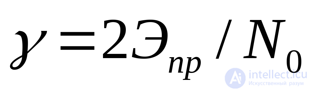 ) and is determined by the energy of the probing signal, all other conditions being equal. It follows that improving noise immunity requires a substantial increase in the energy of the probing signals. However, this conflicts with the requirement of ensuring radar covertness. The conflict can be resolved by using complex-modulated probing pulses with a wide spectrum. This measure can force the enemy to radiate active jamming over a wide frequency band, which (for a fixed jammer transmitter power) will reduce the power spectral density of the jamming
 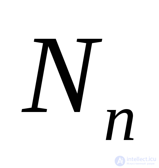 . (Under jamming,
  ).
).
In addition, the following are used to improve radar noise immunity:
Improving radar jamming immunity under masking passive interference (both intentional and unintentional) is achieved in two ways:
Reducing the radar pulse volume reduces the mean RCS of the passive interference and, consequently, the energy of the signal reflected from the passive interference. The influence of the probing signal parameters on the radar pulse volume was considered above. Velocity resolution makes it possible to extract the useful signal against the background of passive interference owing to the difference in radial velocities, using the Doppler effect. When the influence of probing signal parameters on velocity resolution is taken into account, one must speak of the need for simultaneous resolution in range and velocity. Thus, the two-dimensional autocorrelation function of the signal must be required to be narrow both along the time axis ( ) and along the frequency axis (
 ), which amounts to overcoming the uncertainty principle known in radar theory.
This requirement is met most fully by coherent bursts of complex radio pulses.
In the technical implementation of MTI systems, various designs of coherent-pulse radars are possible:
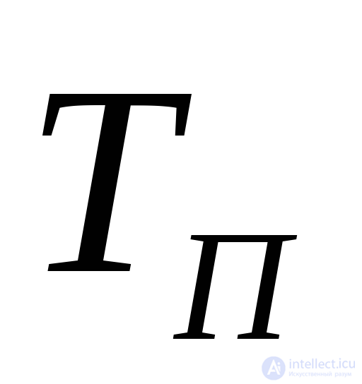 );
);The choice of a particular probing signal structure in a radar is governed by the effectiveness requirements of the MTI systems. Truly coherent probing signals make it possible to achieve large values of the clutter suppression (cancellation) ratio in an MTI system (40 dB or more). Pseudo-coherent probing signals are used when no stringent requirements are placed on the MTI system and the decisive factor is the simplicity of the technical implementation of the radar transmitter hardware.
The analysis carried out above shows that the structures and parameters of probing signals have a significant influence on the tactical and technical characteristics of a radar, and that this influence on the various characteristics is not uniform.
To increase the radar range and the accuracy of coordinate and velocity measurement, it is necessary to increase the energy of the received signal, which, at a fixed pulse power, requires increasing its duration and the duration of the burst of echo signals.
To improve range resolution, the spectral width of the radio pulse should be increased, and to improve velocity resolution, its duration should be increased. Simultaneous resolution in range and velocity (in Doppler frequency) is possible through the use of wideband (complex) radio pulses.
To ensure radar immunity to passive interference through the use of MTI systems, a coherent sequence of radio pulses must be used.
Radar immunity to active jamming depends on the energy of the received signals, for which wideband signals must be used, and also on the radar's ability to rapidly change such signal parameters as carrier frequency and polarization.
The dependence of the main tactical and technical characteristics of a radar on the wavelength (carrier frequency) of the probing signals is complex and non-uniform. Taking all factors into account, it proves expedient to use the metre-wave band in long-range surveillance radars, and the centimetre band and the adjoining part of the decimetre band in radars for detection, guidance and target designation for the active branches of the Air Force and Air Defense Forces, and in radars for detecting low-altitude targets.
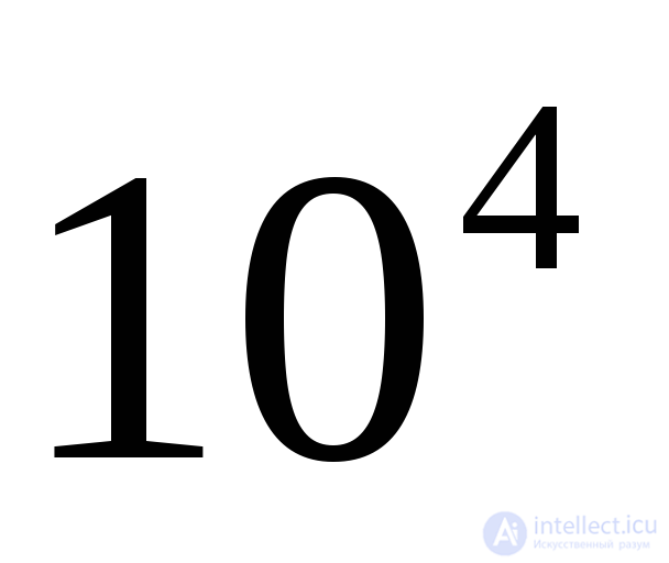
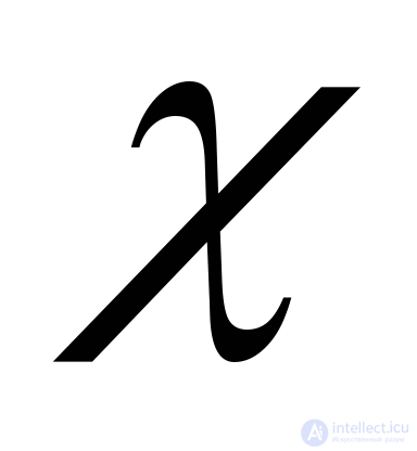 , Hz
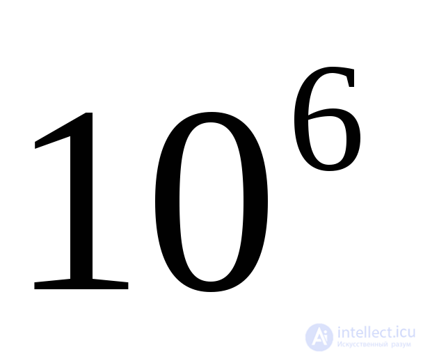
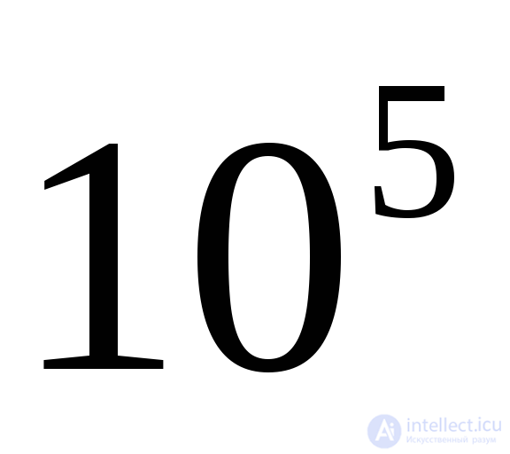
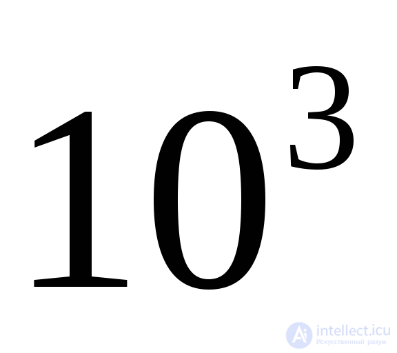
, Hz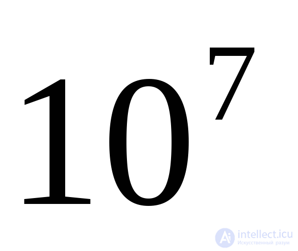

Comments