
Lecture 19 min.
Radio engineering systems (RES) are a class of information-control systems that transmit, extract, or destroy information by means of radio waves. In general, an RES includes a radio transmitting device and a radio receiving device
Any radio engineering system conveys information through a radio channel. Fig. 1.1 shows the generalized composition of the channel.
Carrier-frequency generator 1 produces high-frequency (HF) electrical oscillations. Information from source 2 is superimposed on them, or, in other words, modulation takes place in element 3. The carrier, which now contains the information, is converted in antenna 4 into electromagnetic waves and propagates through space. Part of them reaches receiving antenna 5 and is converted into electrical oscillations, which are then amplified in receiver 6. Detector 7 extracts the information and passes it to the consumer, the information receiver 8. Besides the information transmitted from source 2, while passing through space the radio wave also acquires the properties of that space. These can be either useful or harmful for the main task at hand.
From this, two kinds of radio engineering systems can be distinguished: systems for transmitting and receiving information, and systems in which information is extracted from a carrier that has passed through the medium.
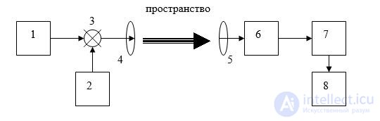
Fig. 1.1. General structure of a radio channel: 1 – carrier generator; 2 – information source; 3 – device for superimposing information on the carrier; 4, 5 – transmitting and receiving antennas; 6 – carrier receiver; 7 – information detector; 8 – information receiver.
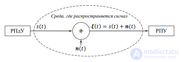
Fig. 1.2. Generalized block diagram of an RES
An RES includes a radio transmitting device (transmitter) and a radio receiving device (receiver). The signal radiated by the transmitter propagates in the external medium, where it is affected by interference, which disrupts its information structure. A signal is regarded as a physical process that carries information. On
the receiving side it is available only in an additive mixture with interference, and the task of the receiver is to extract, with the highest possible reliability, the useful information contained in the signal. (Information extraction is understood to mean the procedures of detection, discrimination, or estimation of signal parameters.)
The first kind includes radio communication systems, radio and television broadcasting, and others. The second kind includes radar and radio navigation systems. For example, a radar station extracts information from space, an element of which is the illuminated object – the target.
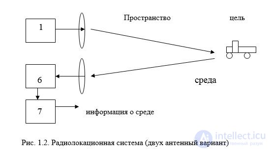
Fig. 1.2. Radar system (two-antenna configuration)
The main indicators of a radio engineering system include:
The characteristics of an RES are considered as tactical and technical characteristics.
Tactical characteristics determine the functional capabilities of an RES in practical use. Let us list the main tactical characteristics of an RES.
1. Quality indicator of the RES. The quality of a detection RES is characterized by the probabilities of correct target detection and of false alarm. The probability of correct detection is the probability of the event in which the system decides that a target is present, given that the target is actually
present in the working zone. The probability of false alarm corresponds to the event in which a decision is made that a target is present, given that no target is present. The quality of a signal-discrimination RES is characterized by the probability of erroneous discrimination of signals, that is, the probability that the discriminator made a wrong decision about which of the signals was transmitted. When estimating signal parameters, the quality of the system is characterized by the variance of the parameter estimate.
2. Working zone of the RES. This is the part of space in which the system provides quality indicators no worse than specified. The working zone is determined by the operating range of the RES, which is the maximum distance at which quality indicators no worse than specified are provided.
3. Resolution. This is the ability of an RES to separately detect or measure the motion parameters of two closely spaced objects. Resolution is evaluated by the minimum distance between two separately detectable objects or by the minimum difference in the values of separately measured parameters.
4. Noise immunity. This is the minimum signal-to-noise ratio at which the RES provides quality indicators no worse than specified.
The technical characteristics of an RES include:
1. Methods of scanning the working zone and determining target coordinates;
2. Type of signals used, spectrum width, operating frequencies and their stability, transmitter power.
3. Sensitivity, dynamic range, and bandwidth of the receiver.
4. Shape and width of the antenna radiation pattern, and its directivity.
A characteristic feature of an RES is the use of a radio signal as the information carrier. According to the type of signals used, continuous, pulsed, and digital radio engineering systems are distinguished.
In continuous (analog) RES, information is represented by continuous variation of one or several parameters
of the carrier oscillation, such as amplitude, frequency, or phase.
In pulsed RES, the signal is a sequence of radio pulses in which information can be represented both by the parameters of individual pulses (frequency, phase, duration) and by the parameters of the sequence itself (the number of pulses in the sequence, the interval between them).
In digital RES, the analog signal carrying the information is converted into a digital one, which modulates the carrier oscillation.
By purpose, RES are divided into:
Information transmission RES are intended for transmitting information from one point in space to another. They include radio communication, telemetry, radio broadcasting, and television systems.
Information extraction RES are intended for extracting information about some object. They include radar and radio navigation systems, as well as systems for radio reconnaissance of the enemy's radio-electronic equipment.
Radar combines the methods and technical means of detecting objects and measuring the parameters of their motion, based on the use of radio waves. Radar measurements are based on processing signals reflected from an object (a radar target) or radiated by the object.
Radio navigation covers radio engineering methods of navigating ships, aircraft, and other mobile objects. Radio navigation measurements are based on processing signals radiated by special radio transmitting devices (radio beacons) whose location is known.
Radar and radio navigation are closely related by the commonality of the tasks they solve: determining the coordinates of objects and the parameters of their motion.
Radio reconnaissance (ELINT/ESM) includes methods and technical means for detecting the fact that enemy radio-electronic equipment is actively operating, determining its location, and also measuring the parameters and analyzing the structure of the signals it uses.
The main tasks solved by information extraction RES include:
Information destruction RES are intended to create
conditions that hinder or make impossible the operation of enemy radio-electronic equipment.
Radio control RES are intended for remote
control of the operation of various objects by means of radio signals, and combine information transmission and extraction.
The signal processing carried out in the receiving devices of an RES in accordance with their purpose includes the solution of the following tasks:
The signal detection task is characteristic of radar object-detection systems. The transmitter radiates a signal of known form. When a radar target is present in the coverage zone of the RES, the signal is reflected from the target and, mixed with interference, arrives at the input of the receiver. When no object is present, only interference is present at the receiver input. The receiver is required to decide, in an optimal manner (according to some criterion), whether a signal is present or absent at the input.
The signal discrimination task is characteristic of digital information transmission RES. The information to be transmitted is represented in binary form, that is, as sequences of two symbols. Each symbol is assigned a signal that differs from the others (in shape or parameters), and these signals, propagating from the transmitter to the receiver, are distorted by interference. The receiver of the information transmission system is required to determine which of the signals arrived at the input. On this basis a decision is made about which of the symbols was contained in the current position of the transmitted information message. In the more general case, discrimination among more than two signals is considered.
The parameter estimation task is characteristic of RES that measure the coordinates of objects and the parameters of their motion. In range measurement, the transmitting antenna of the system radiates a signal at a known moment in time; the signal propagates toward the target and, reflecting from it, arrives at the input of the receiving antenna. Measuring the signal delay time makes it possible to determine the range to the target. To measure the radial velocity of the target, it is necessary to measure the shift of the carrier frequency of the radio signal.
The tasks considered are closely interrelated.
Signal detection can be regarded as discrimination between two signals, one of which is zero and the other is the signal being detected. In parameter estimation, one can formally introduce an ensemble of signals that differ from each other in the possible values of the parameter being estimated. Then, to estimate the parameter it is sufficient to indicate which of the signals of the ensemble arrives at the input of the receiver, so the task reduces to signal discrimination. Detection and parameter estimation of signals are carried out under the influence of interference and with uncertainty regarding the radar targets. Discrimination of signals in information transmission systems is carried out against a background of interference, and the probability of occurrence of each
of the signals to be discriminated at the receiver input is determined by the properties of the information source. This means that these tasks must be treated using the methods of probability theory.
Radar is a field of science and technology that combines the methods and means of location (detection and measurement of coordinates) and of determining the properties of various objects by means of radio waves. A closely related and partly overlapping term is radio navigation; however, in radio navigation the object whose coordinates are being measured plays a more active role, most often the task being determination of its own coordinates. The main technical device of radar is the radar station (radar set, English: radar).
A distinction is made among active, semi-active, active with passive response, and passive radar. Radars differ by the radio-wave band used, by the type of probing signal, by the number of channels used, by the number and type of coordinates measured, and by the installation site of the radar.
Active radar is of two types:
By purpose, radars can be classified as:
By field of application, a distinction is made between
By type of platform:
By mode of operation:
According to the type of emission, radars are divided into:
By wavelength band:
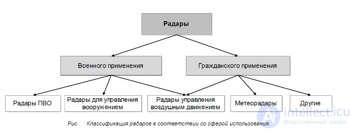
Fig. . Classification of radars according to field of use.
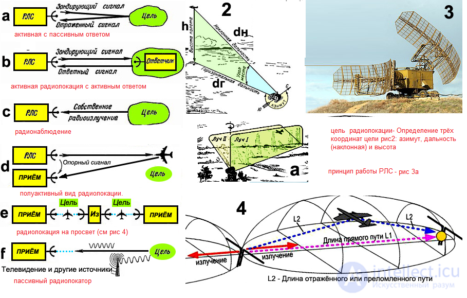
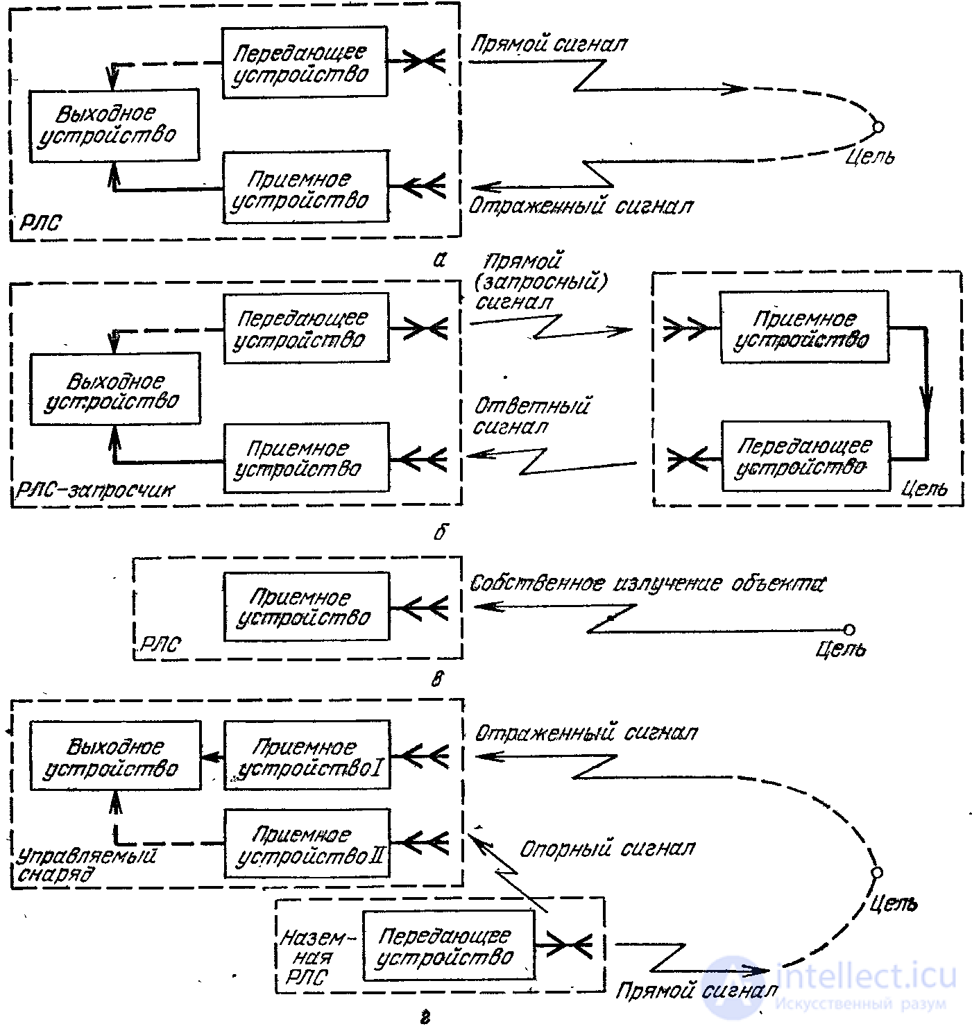
Fig. 1.6. Simplified diagrams of radar signal formation:
a – active location with passive response; b – active location with active response; c – passive location; d – semi-active location
Thermal radar (radiometric location) uses the objects' own emission caused by the thermal motion of electrons.
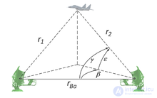
Block diagram of a bistatic radar
A bistatic radar is a radar system consisting of a transmitter and a receiver that are separated by a distance comparable to the expected distance to the target. Conversely, a radar in which the transmitter and receiver are co-located is called a monostatic radar. A system containing several spatially separated monostatic radars or bistatic radar components with a common coverage area is called a multistatic radar. Many long-range air-to-air and surface-to-air missile systems use semi-active radar homing, which is a variety of bistatic radar.
Some radar systems may have separate transmitting and receiving antennas, but if the angle between the transmitter, the target, and the receiver (the bistatic angle ) is close to zero, they will still be considered monostatic or pseudo-monostatic . For example, some very long-range HF radar systems may have the transmitter and receiver separated by several tens of kilometers to provide electrical isolation, but since the expected operating range is on the order of 1000-3500 km, they are not considered truly bistatic and are called pseudo-monostatic.
In some configurations, bistatic radars can be designed to operate as a fence, detecting targets passing between the transmitter and the receiver, with a bistatic angle of about 180 degrees.. This is a special case of bistatic radar known as forward-scatter radar, after the mechanism by which the transmitted energy is scattered by the target. In forward scatter, the scattering can be modeled using Babinet's principle and is a potential countermeasure against stealth aircraft, since the radar cross section (RCS) is determined solely by the silhouette of the aircraft as seen by the transmitter, and is not affected by stealth coatings or shapes. The RCS in this mode is calculated as σ = 4πA² / λ², where A is the silhouette area and λ is the radar wavelength. However, the target can vary from location to location, and tracking is very problematic in forward-scatter radars, since the information content of the range, bearing, and Doppler shift measurements becomes very low (all these parameters tend to zero, regardless of the target's location in the fence).
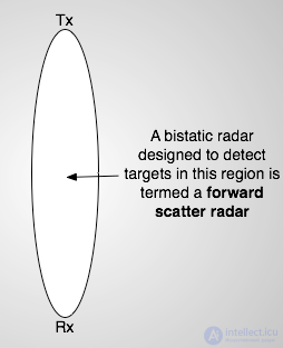
Illustration of forward-scatter geometry
A multistatic radar system is a system that has at least three components, for example one receiver and two transmitters, or two receivers and one transmitter, or several receivers and several transmitters. It is a generalization of a bistatic radar system, with one or more receivers processing signals from one or more geographically separated transmitters.
A bistatic or multistatic radar that uses non-radar transmitters of opportunity is called a passive coherent location system or passive covert radar .
Any radar that does not send out an active electromagnetic pulse is known as a passive radar. Passive coherent location, also known as PCL, is a special type of passive radar that uses transmitters of opportunity, especially commercial signals in the environment.
The main advantages of bistatic and multistatic radar include:
The main disadvantages of bistatic and multistatic radars include:
Passive radar systems (also called passive coherent location, passive surveillance systems, and passive covert radar ) encompass a class of radar systems that detect and track objects by processing reflections from non-cooperative sources of illumination in the environment, such as commercial broadcast and communication signals. This is a special case of bistatic radar, the latter also including the use of cooperative and non-cooperative radar transmitters.
Typical illuminators
Passive radar systems have been developed that use the following sources of illumination:
Analog television signals
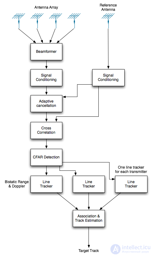
In a traditional radar system, the time of pulse transmission and the shape of the transmitted signal are precisely known. This makes it easy to calculate the distance to an object and to use a matched filter to achieve the optimal signal-to-noise ratio at the receiver. A passive radar does not have this information directly and therefore must use a dedicated receiver channel (known as the "reference channel") to monitor each transmitter being used and dynamically sample the transmitted signal. A passive radar typically uses the following processing stages:
These are described in more detail in the sections below.
Proponents of the technology cite the following advantages:
Opponents of the technology cite the following disadvantages:

Comments