
Lecture 14 min.
The basic radar equation — a formula describing the operating range of a radar through the calculation of radio signal power and various losses. For most active radars, which are monostatic (the transmitting and receiving antennas are located close together or are combined), the received signal power is inversely proportional to the 4th power of the distance to the target, while for passive radars the signal power is inversely proportional to the 2nd power of the distance.
What is the radio communication range and what does it depend on? To answer this question, we need to recall the role played by the transmitter and receiver antennas. The transmitter antenna not only radiates radio waves but also concentrates the power of the beam in the required direction. This function is characterized by the antenna gain Ga . Indirectly, this value is related to the antenna beamwidth Qa , or its directivity, as well as the efficiency η (which reflects the losses in the transmission line and the aperture utilization factor of the antenna structure).
The amount of energy intercepted by the antenna of a radio receiver depends on the area of the receiving antenna Sa. This, in turn, is also related to the gain and the wavelength λ. The wavelength has to be taken into account because at a shorter wavelength a higher gain can be obtained with the same area, although the radio wave interception capability remains the same. Let us present the relations known from antenna theory and, in justified cases, also use empirical relations for engineering calculations.
The maximum range of a radar is the limiting distance to a target at which detection of the signal reflected from the target against the noise background is ensured with a given probability.
The range of a radar in free space (neglecting the influence of the ground and the atmosphere) depends primarily on its main parameters, and on the properties and size of the illuminated object, i.e. the target.
Radar parameters
|
- pulse transmitter power |
- |
Pt |
|
- receiver sensitivity |
- |
Pr.min |
|
- antenna gain |
- |
G |
|
- effective antenna area |
- |
Sa |
Target parameters
|
- radar cross section (RCS) of the target |
σ |
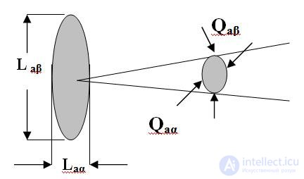
Fig. 1. Parameters of a reflector antenna
Directivity = 360° 360° / [Qaα o Qaβo ]; Ga = Directivity *η ; Sa = Ga λ2 / (4π) (1)
Ga ≈ (10-25) 103 / (Qaα o Qaβo ) ; Laβ ≈ (60-80) λ/ Qaβo ; Laα ≈ (60-80) λ/ Qaαo
Examples:
| Antenna type | gain |
| Reflector 1.5x3.5 deg, 2 cm | 3500 |
| Half-wave dipole | 1.5 |
| Quarter-wave monopole | 1 |
An important indicator of the radio communication range is the power flux density γ. It shows how many watts of radio wave power fall on one square meter of the surface of the radiation sphere.
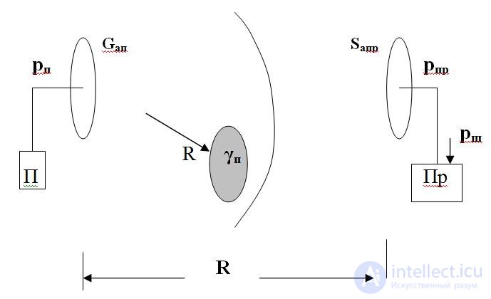
Fig. 2. On the derivation of the radio link equation
A point source radiates spherical radio waves. At a distance R from it, the transmitter signal power in the antenna pt is divided over the whole area of the sphere 4π R2. Therefore, each square meter of the sphere receives a power flux density γt = pt / (4π R2 ). If the antenna has a known gain Gat , the flux density increases by the same factor γt = pt Gat / (4π R2 ).
pr = Sar pt Gat / (4π R2 ) = pt Gat Gar λ2 / (4π)2 R2 (2)
Relation (2) is the first form of the radio link equation. It can be used to calculate the signal power at the input of the receiver of the receiving station. But we must not forget that electrical noise is generated in the receiver. Its power can be referred to the input, as was shown earlier in lecture LekzRT1.3 . The power of the input-referred noise pn in watts is calculated taking into account the frequency bandwidth of the receiver ∆Fr and its noise properties.
pn = nn2 ∆Fr ; pn = NkT ∆Fr (3)
In equalities (3), nn is the spectral density of the noise voltage at the input in V/Hz, nn2 – the same on the W/Hz scale. N – is the receiver noise figure, kT - are the Boltzmann constant and the equivalent noise temperature of the receiver in degrees Kelvin.
The power spectral density nn2 can be found in reference books on receivers, as can the noise temperature. The noise figures of receivers are also among the important characteristics and are given in the product datasheets.
Let us return to the probabilities of detection Pd and false alarm Pfa . Both depend on the signal-to-noise ratio and on the threshold level Uth of the automatic detector. Engineers have optimized the threshold level for various requirements on Pd and Pfa and obtained the so-called receiver operating characteristics. Their form is given in Fig. 3.
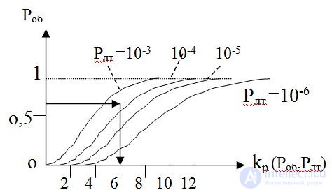
Fig. 3. Receiver operating characteristics

The potential for high-quality information reception depends on the discriminability factor kd (Pd,Pfa) of the signal against the noise background, that is, on the signal-to-noise ratio provided by the radio transmission channel. Fig. 3 gives an example of how the required signal-to-noise ratio is estimated as a function of the specified values of Pd,Pfa. Thus, the transmitter power Pt for known antenna characteristics and wavelength must be such that the value found from the curves in Fig. 3 is ensured kd. That is, the condition pr >= kd pn.must be satisfied. Taking the latter into account, we can obtain the second form of the radio link equation, from which the operating range of the radio link can be calculated.
The receiver sensitivity characterizes its ability to receive weak signals (the lower the power of the received signals, the better the sensitivity). The gain and effective area of the antenna characterize its focusing properties.
Suppose the radar transmitter is located at point "O" (Fig. 2.1 ), and the target is located at a distance R at point "O".
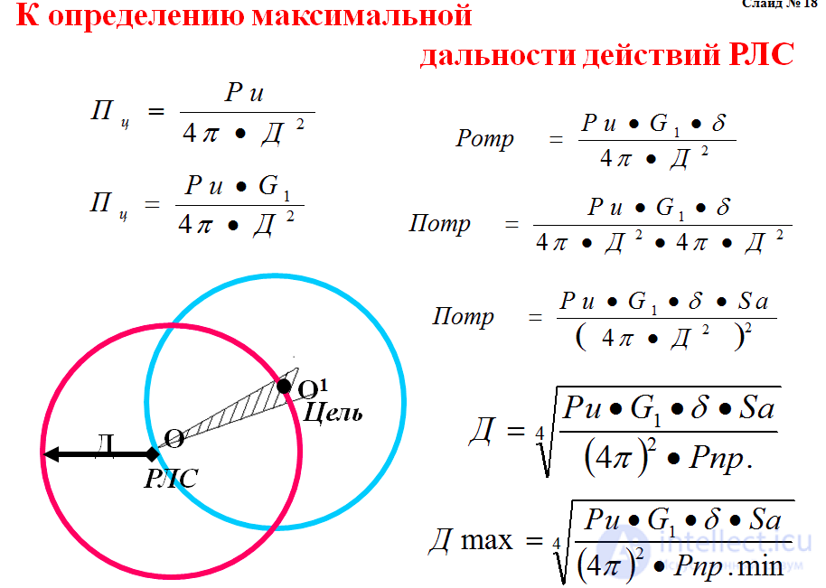
Fig. 2.1
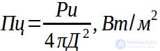
Then the power flux density Πt at a distance R (at point O1) for an omnidirectional radar transmitting antenna can be found by dividing the radiated power Pt by the surface of a sphere of radius R, equal to 4πR2
 .
.
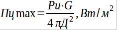
With directional radiation, the power flux density at the target Πt increases by a factor of G. Consequently, Πt in the direction of maximum radiation will be equal to:
 .
.
If a target with a radar cross section (m2) is located in the direction of maximum radiation of the antenna, then the power reflected from the target Prefl is equal to:
 .
.
The radar cross section of a target is understood as the surface area which, with uniform scattering of energy in all directions, gives the same intensity of the reflected signal at the receiving location as the real target.
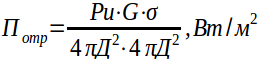
The reflected power flux density Πrefl at a distance R from the station can be obtained by dividing the reflected power Prefl by the surface of a sphere of radius R
 .
.
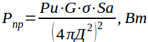
Thus, we have established that each unit area of the radar receiving antenna receives a reflected power flux density equal to Πrefl.
Given that the effective antenna area is Sa, m2, the total reflected signal power received by the radar antenna Pr will be equal to
 .
.
From the last formula we determine the radar range
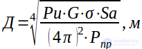 .
.
The maximum range of a radar is determined by the minimum required reflected signal power Pr at the receiver input at which the reflected pulse can be distinguished on the indicator screen. This is nothing other than the sensitivity of the radar receiver Pr.min. Substituting this value into the radar range equation, we obtain
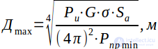 (1)
(1)
This expression is called the basic radar equation for free space. It shows the dependence of the radar range on the station parameters and the nature of the target.
Let us consider the influence of the radar's technical parameters and of the target's radar cross section on the radar's range.
A. Influence of transmitter parameters (Pt)
From equation (1) it follows that
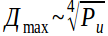 ,
,
i.e. the greater the radiated power Pt, the greater the radar range. However, the fourth root shows that a significant increase in range can be obtained only through a very large increase in transmitter power. Thus, to double Rmax the radiated power must be increased 16 times (24 = 16).
B. Influence of antenna parameters (G and Sa)
In a radar, a single antenna is used for transmitting and receiving energy, for which the gain G and the effective area Sa are interrelated by the following relation
 or
or 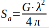 .
.
Substituting the value of Sa into equation (1), we obtain
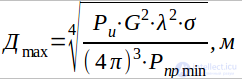 or R max ~
 .
.
It follows that increasing G is a more effective way of increasing R max.
For a fixed wavelength λ, an increase in G is achieved by increasing the effective antenna area Sa, which is proportional to the geometric dimensions of the antenna Sg:

where – the antenna aperture efficiency (geometric area utilization factor).
For multi-dipole array antennas k = (0.3...0.4), for parabolic antennas k = (0.5...0.7).
Increasing Sg is limited by design considerations.
C. Influence of receiver parameters (Pr.min)
The receiver sensitivity Pr.min determines the minimum reflected signal power at the receiver input at which the signal at the receiver output is distinguishable against the noise background. It is related to the operating range by the relation
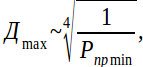
from which it follows that Rmax is greater the higher the receiver sensitivity (that is, the smaller the absolute value of Pr.min..
D. Influence of the target radar cross section (σ)
The target radar cross section σ takes into account:
the size of the target surface oriented relative to the radar antenna radiation pattern;
the radar wavelength λ;
the reflection coefficient of the material the target is made of;
the shape of the target.
Since σ of a complex object (a missile, an aircraft, etc.) is rather difficult to calculate, in practice it is determined experimentally. In calculations, the following data can be used, in m2.
|
Objects |
Centimeter-wave radar |
Meter-wave radar |
|
Heavy strategic bomber |
30 |
70 |
|
Fighter-bomber |
5...8 |
15...20 |
|
Air-to-ground missile: |
|
|
|
SRAM |
0.01...0.1 |
0.5...2.5 |
|
SCAD |
0.1...1.0 |
1.0...5.0 |
|
Unmanned reconnaissance aircraft |
0.1...0.2 |
|
|
Automatic balloon |
0.5...0.7 |
The relationship between the radar range and the target parameters is shown by
 , which shows that as σ increases the detection range increases, because the power of the reflected signal increases.
Note. Point out to the students that a potential adversary, when developing new aircraft, strives to reduce the radar cross section.
At present, air defense radars detect targets with a minimal radar cross section.
The power of the received echo of the radio signal is given by the equation :

Notation:
When the transmitting and receiving antennas are located at the same distance from the target, that is, in all monostatic radars (single-site radar systems) and sometimes in other types, the formula is simplified by setting Rt = Rr = R, which leads to the factor R4:
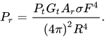
Thus, the received power decreases in proportion to the 4th power of the distance.
The factor F can be taken equal to 1 if the wave is assumed to propagate in a vacuum without losses and without interference.
The minimum power at which the receiver can detect the signal reflected from the target is given by the formula

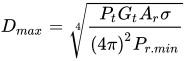 ,
,
where:
 — transmitter power;
 — antenna directivity;
 — effective antenna area
 — radar cross section of the target
 — minimum receiver sensitivity.
The active response comes from a radar transponder (repeater) installed on the target.
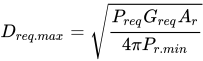
Maximum range on the interrogation channel
Maximum range on the response channel
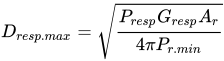
With an active response, the distance enters the formulas to the power of 2, not 4, since the transponder power is fixed and does not depend on the power of the radar radiation incident on the "target". In the case of a passive response, the target, according to the Huygens-Fresnel principle, acts as a secondary re-radiator whose power is directly proportional to the radar radiation incident on it. Thus, in passive radar ranging, the signal from the radar transmitter is attenuated by a factor of  on the way to the target, is reflected, and then on the way from the target to the radar receiver is attenuated by a further factor of
  . As a result we obtain the factor
  , and in the case when Rt = Rr = R, this factor equals
  .
.
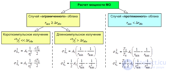
The range against clutter is significantly reduced with low-PRF pulsed emission. Moreover, this reduction is most pronounced against clutter from surface-distributed reflectors.
The transition to quasi-continuous emission is preferable when the target is in the clutter zone at ranges up to the radio horizon.
At long ranges, or when observing a target outside the clutter zone, the use of a pulsed signal is preferable.
The greater the radiated power Pt, the gain G and effective area of the antenna Sa , and the radar cross section of the target σ, and the smaller the absolute value of the receiver sensitivity Pr.min, the greater the radar range.
The greatest effect for increasing Rmax is provided by increasing the geometric dimensions of the antenna G and Sa, where to double Rmax it is sufficient to increase the antenna area by a factor of 4. But the geometric dimensions are limited by the design features of antenna devices. The least effect for increasing Rmax is provided by increasing Pt ,σ, Pr.min , since to double Rmax they must be increased 16 times.

Comments