
Lecture 11 min.
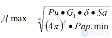
The basic radar equation considered above, intended for calculating the range of a radar station, is valid only if there is a line of sight between the station and the target. The factor limiting the line-of-sight range to a target, and hence the possible range of its detection, is the curvature of the Earth's surface (Fig. 2.2).
Since radio waves propagate in straight lines, a radio shadow forms below the horizon line (AC). If a target is below the horizon line (T2), it will not be detected by the radar, even though the radar's line-of-sight range may greatly exceed the distance to that target. Only targets located above the horizon line (T1) will be detected, provided the distance to them does not exceed the range of the station.
The maximum line-of-sight range Dlim depends on the antenna height ha and the target height Ht above the Earth's surface. The maximum line-of-sight range Dlim can be determined as

where RE is the radius of the Earth's surface, equal to 6375 km.
Since RE is many times greater than ha and Ht, then

Substituting the value RE = 6375 km into this formula, we obtain
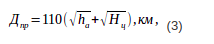
where Dlim, ha and Ht are expressed in kilometres.
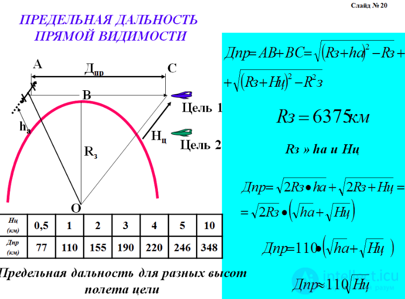
Fig. 2.2
When a ground-based radar operates against airborne targets, Ht >> ha
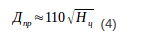
Table of Dlim for different target flight altitudes
|
Ht, m |
500 |
1000 |
2000 |
3000 |
4000 |
5000 |
10 000 |
|
Dlim, km |
77 |
110 |
155 |
190 |
220 |
246 |
348 |
From formula (4) and the table it can be seen that low-flying targets can be detected at shorter ranges than high-flying ones.
Dmax for radars operating in an anti-aircraft defense system does not exceed 500...600 km (Ht = 20...25 km. Ht for very-long-range detection radars of a BMD system reaches 5000 km or more (Ht of missiles = 1000 km or more. To increase the range of ground-based radars, the antenna is usually placed on elevated ground. Formula (3) is valid for free space, without taking into account the influence of the atmosphere on radio wave propagation.
The preceding sections considered the factors that determine radar range in free space. However, the real conditions of radio wave propagation, owing to the presence of the atmosphere and the ground, differ from those in free space, which naturally also affects the radar detection range Dmax.
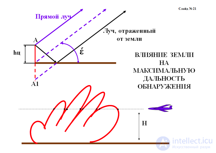
The reflection of radio waves from the Earth's surface has an effect mainly in the metre-wave band, since specular reflection predominates in this band. With specular reflection, in addition to the direct ray from the station, a ray reflected from the ground also reaches the target (Fig. 2.3, slide 15, 20).
The phase relationship between the direct ray and the ray reflected from the ground depends on the elevation angle ε) at which the ground lies relative to the station. If the direct wave and the wave reflected from the target are in phase, the station's range Dmax turns out to be greater than that calculated by formula (1) (see the equation for the maximum radar range in free space), and if they are in antiphase, Dmax decreases. When calculating Dmax from the basic radar equation, corrections (coefficients that take into account the influence of the ground) are introduced.
When the ray reflected from the ground is taken into account, the antenna radiation pattern in the vertical plane acquires a lobed character (Fig. 2.3, slide 15, 20).
The number of lobes, their positions and the depth of the nulls depend on the height of the antenna above the ground (in wavelengths, that is, on the ratio λ/ha), the polarization of the wave and the properties of the soil.
With a perfectly conducting surface (a smooth sea surface), the energy of the ray reflected from the ground equals the energy of the direct ray. Therefore, the maximum values of the field strength double, while the minimum values fall to zero. In other cases the electromagnetic energy is absorbed in the ground, and the ray reflected from the ground has less energy than the direct ray (usually E_ref = (0.8...0.9)E_inc). Therefore, in the directions of the lobe maxima the field strength increases by less than a factor of two, and in the directions of the minima it does not fall to zero. The lobed character of the radiation pattern causes "nulls" at certain elevation angles ε, as a result of which at some ranges there is no signal reflected from the target and tracking it becomes difficult.
When centimetre-band radio waves are used in a radar, diffuse reflection from the Earth's surface occurs. Only the direct ray from the radar reaches the target, which eliminates the difference in field strength at different elevation angles and the lobed character of the radiation pattern. Therefore, for centimetre-band radars the basic radar equation (1) (see the 1st study question) does not require corrections for ground reflection.
The influence of the curvature of the Earth's surface on radar range was considered in the second study question; it is limited by the line-of-sight range Dlim.
The influence of the atmosphere is manifested in:
Refraction and superrefraction
RADIO WAVE REFRACTION (bending of radio waves) is a change in the direction of propagation of radio waves in an inhomogeneous medium whose refractive index depends on coordinates and time. At a plane interface between two homogeneous media with refractive indices n1 and n2 a plane wave is refracted according to Snell's law of refraction , where
 is the angle of incidence,
 is the angle of refraction of the wave. The amplitude of the refracted wave depends on its polarization and is determined by the Fresnel formulas (see Reflection, radio waves).
SUPERREFRACTION is a phenomenon of inversion of the height profile of the reduced (taking into account the sphericity of the Earth's surface) refractive index for radio waves propagating over the Earth's surface .It leads to the formation of a tropospheric duct for VHF and to a significant extension of the radio horizon.
A radio wave propagates in a straight line and at constant speed only in a homogeneous medium, in particular, in a dielectric with a constant permittivity ε. Meanwhile, with increasing distance from the ground, the temperature, humidity and air pressure change (decrease), especially within the first ten kilometres.
As a result, the dielectric permittivity of the air layer decreases with increasing altitude. This causes the radio wave propagation path to be bent toward the ground by the various layers of the atmosphere. This phenomenon is called "refraction".
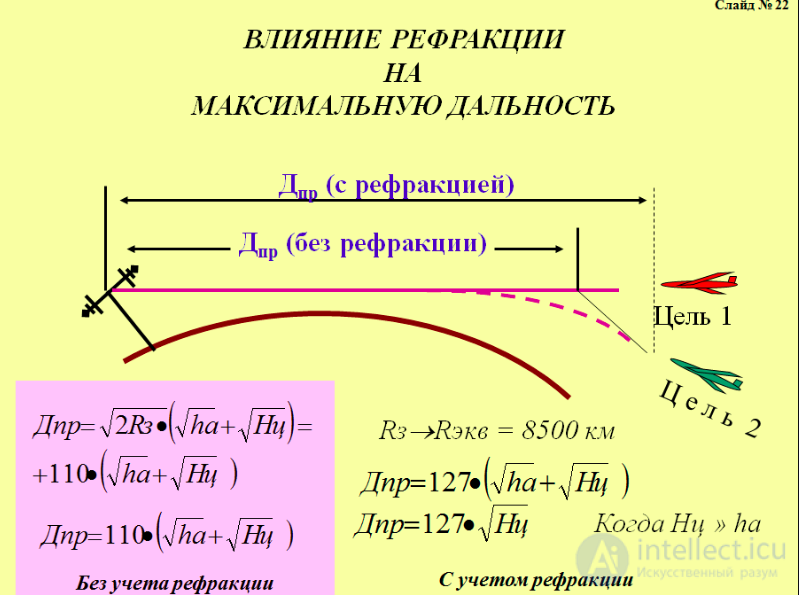
Owing to refraction, the radar range increases and it becomes possible to observe targets located below the horizon line (T2) (Fig. 2.4, slides 16, 21).
The increase in the maximum line-of-sight range Dr can be accounted for by changing the coefficient in formula (3) (see the 2nd study question)

Under the so-called standard state of the atmosphere (normal refraction), the value RE is replaced by the equivalent Earth radius REe = 8500 km.
REe – the equivalent radius of an imaginary Earth for which the electromagnetic ray, under the influence of refraction, propagates in a straight line.
With refraction taken into account, the line-of-sight range Dr is determined with sufficient accuracy by the formula
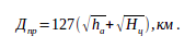
For ground-based radars, when Ht >> ha , then
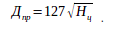 .
.
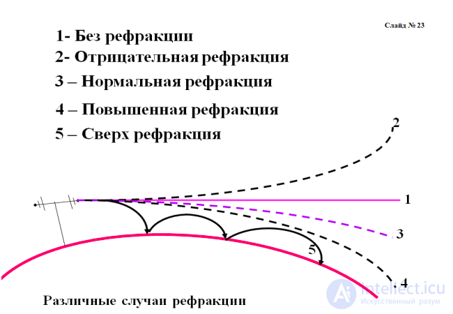
With a sharp decrease in humidity and a considerable difference in air temperature and pressure (with altitude), ultra-short radio waves follow the Earth's surface owing to multiple reflection from the lower layers of the atmosphere (Fig. 2.5, slides 17, 22).
The lower layer of the atmosphere together with the Earth's surface forms a kind of waveguide that guides the flow of electromagnetic energy. This phenomenon is called superrefraction (Fig. 2.5–5). With superrefraction, the detection range reaches about 2500 km, whereas the line-of-sight range is only a few tens of kilometers.
However, the atmospheric conditions that cause superrefraction occur irregularly and comparatively rarely, usually in the summer months in subtropical and tropical zones, mainly over bodies of water.
Absorption and scattering of radio wave energy in the atmosphere are caused by the presence of oxygen and water vapor in it; that is, the atmosphere is not radio-transparent. As a result of absorption and scattering, the energy carried by a radio wave continuously decreases along its propagation path – this is radio wave attenuation.
Two types of attenuation are distinguished:
At long wavelengths, absorption and scattering can be neglected. At wavelengths λ< 10 cm these phenomena become significant, and radio wave energy losses increase as the wavelength becomes shorter.
Resonant absorption and scattering cause the radar's Dmax to decrease sharply at certain wavelengths. Oxygen introduces particularly significant attenuation at wavelengths λ = 0.25 cm and λ = 0.5 cm, and water vapor at wavelengths λ = 0.17 and 1.3 cm (Fig. 2.6, slides 18, 23).

Fig. Calculation of radar range in the presence of clutter from volume-distributed reflectors
The range in the presence of clutter is significantly reduced with low-PRF pulsed emission. This reduction is most noticeable in the presence of clutter from surface-distributed interference.
A transition to quasi-continuous emission is preferable when the target is located in the clutter zone at ranges up to the radio horizon.
At longer ranges, or when observing a target outside the clutter zone, it is preferable to use a pulsed signal.
Scattering of radio wave energy by the tiniest water droplets means that a cluster of droplets (clouds, rain) produces a reflected signal that can be observed on the radar indicator screen. Thus, reflection from clouds begins to appear at λ = 10 cm and shorter. At wavelengths λ< 3 cm, clouds, rain, and snow create strong interference, sometimes making it impossible to observe the target.
Attenuation of radio waves in the atmosphere mainly affects wavelengths shorter than 30 cm. At λ = 10 cm, the radar range is reduced relative to the calculated value by no more than 3...4% even under unfavorable atmospheric conditions.
Attenuation of electromagnetic wave energy in the atmosphere limits the lower bound of the wavelengths used in radars.
The maximum range of a radar depends on its technical parameters, the target characteristics (σ) , and the influence of the ground and atmosphere.
Because the technical parameters of the station, and even more so the radio wave propagation conditions and target characteristics, are subject to random variations under real operational conditions, the maximum range of a radar is estimated probabilistically. Usually the radar data sheet specifies the value of the maximum range against targets of a certain type (fighter, bomber) with a given probability.
To avoid diffraction (electromagnetic waves bending around the target) and obtain a reflection from the target, the wavelength must be smaller than the linear dimensions of the target, that is, λmax ≤ 5 m, but excessive shortening leads to large absorption and scattering of radio waves in the atmosphere, therefore λmin > 3 cm.
Thus, air defense radars usually operate in the wavelength range
3 cm < λ < 5 m.
When siting a radar, the terrain relief must be taken into account. For meter-wave and decimeter-wave radars, the site should be as level as possible. This helps to increase the radar range and reduce nulls in the antenna pattern). Centimeter-wave radars should preferably be placed on commanding heights.

Comments