
Lecture 18 min.
A radar station (radar; from English radio detection and ranging) is a radio engineering system for detecting air, sea and ground objects, as well as for determining their range, velocity and geometric parameters. It uses the radar method, based on radiating radio waves and registering their reflections from objects. The English term appeared in 1941 as an acronym (RADAR), which later became a word in its own right.
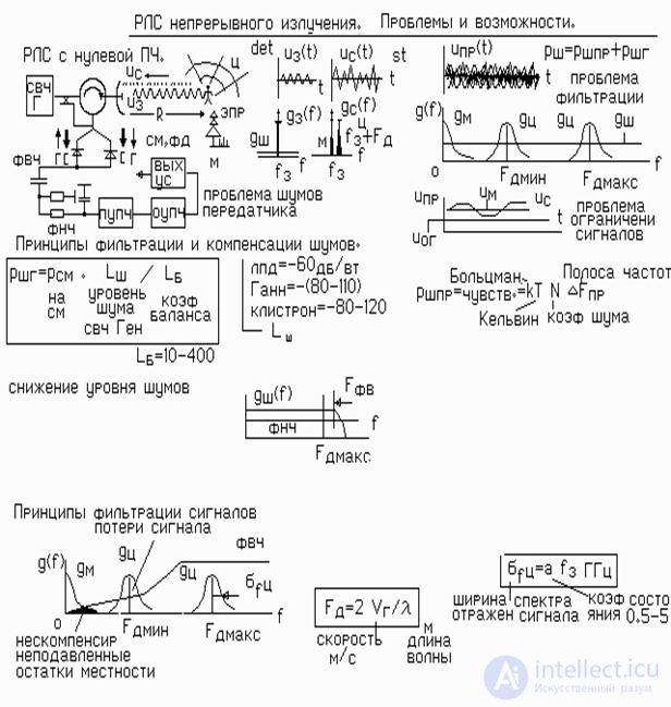
Continuous-wave radars with a monochromatic signal are the simplest and cheapest devices. But a number of difficulties arise in their operation and design. The advantages, disadvantages and problems of radars of this class are examined in this lecture.
The advantages (simplicity and low cost) are obvious.
The figure illustrates the operation of a continuous-wave radar with a monochromatic signal. From the microwave generator of the transmitterthe probing signal of frequency ft is sent through the circulator to the antenna. The reflected signal passes through the circulator to the mixer. A portion of the transmitter microwave voltage is also fed there through the coupler . The reflected signal has the same frequency as the probing one. But its frequency is shifted by theDoppler increment FD. fr = ft+-FD. Of course, passive clutter from the terrain has no Doppler frequencies.
At the mixer, the stochastic reflected signals and the local oscillator voltage are multiplied. And since the local oscillator voltage is constant, a linear conversion of the signals to zero intermediate frequency takes place fIF = ft+-FD - ft =FD. In this case the spectrum of ground clutter lies at zero on the frequency axis, while the spectrum of moving targets is shifted from zero by theDoppler frequency.
For centimeter-wave radars, the value of the frequency FD and the spectrum width lie in the audio-frequency range from 0 to 5 kHz. Therefore the subsequent filtering is performed with inexpensive audio-frequency filters. Thus, ground clutter suppression is easily accomplished with an audio high-pass filter. To reduce the noise level, a low-pass filter can be used whose frequency "cutoff" is matched to the Doppler frequency of a target moving at maximum speed.
Continuous-wave radars with a monochromatic signal have two significant drawbacks.
1. A single radar cannot measure the range to the target.
2. Since the transmitter continues to operate while the reflected signal is being received, transmitter noise reaches the receiver input.
"Noise pumping" occurs. The "pumped" noise adds to the receiver's own noise and can reduce sensitivity by 1-3 orders of magnitude.
At low transmitter powers (up to 10-50 mW), the "pumping" noise may be lower than or comparable to the receiver noise. At such powers the radar range can usually be 3-6 km. If a range of 20 km or more is needed, the transmitter power must be increased sharply. But in that case the "pumping" noise increases sharply as well, and the range practically does not increase!
To increase the range, it is necessary to use low-noise microwave generators and to provide special measures for compensating the "pumping" noise (circulators, balanced mixers, etc.)
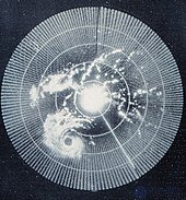

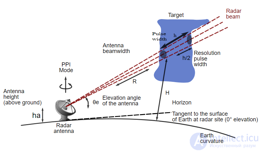

A primary (passive-response) radar mainly serves to detect targets by illuminating them with an electromagnetic wave and then receiving the reflections (echoes) from the target. Since the speed of electromagnetic waves is constant (the speed of light), it becomes possible to determine the range to the target based on measuring various parameters of signal propagation.
A radar station is built around three components: a transmitter, an antenna and a receiver.
The transmitter (transmitting device) is the source of the electromagnetic signal. It may be a high-power pulse generator. For centimeter-wave pulsed radars it is usually a magnetron or a pulse generator built on a master oscillator / power amplifier scheme, most often using a traveling-wave tube (TWT) as the amplifier, while for meter-wave radars a triode tube is often used. Radars that use magnetrons are noncoherent or pseudo-coherent, unlike TWT-based radars. Depending on the range measurement method, the transmitter operates either in pulsed mode, producing repeated short high-power electromagnetic pulses, or radiates a continuous electromagnetic signal.
The antenna radiates the transmitter signal in a given direction and receives the signal reflected from the target. Depending on the implementation, the reflected signal may be received either by the same antenna or by a different one, which can sometimes be located at a considerable distance from the transmitting one. If transmission and reception are combined in one antenna, these two operations are performed alternately, and to prevent the powerful transmitter signal from leaking into the receiver, a special device is placed in front of the receiver that closes the receiver input at the moment the probing signal is radiated.
The receiver (receiving device) amplifies and processes the received signal. In the simplest case the resulting signal is fed to a cathode-ray tube (display), which shows an image synchronized with the motion of the antenna.
Different radars are based on different methods of measuring the parameters of the reflected signal.
The frequency method of range measurement is based on frequency modulation of the radiated continuous signals. In the classical implementation of this method (LFM), the frequency changes linearly from f1 to f2 over a half-period. Because of the propagation delay, the difference between the frequencies of the transmitted and received signals is directly proportional to the propagation time. By measuring it and knowing the parameters of the radiated signal, the range to the target can be determined.
Advantages:
Disadvantages:
The phase (coherent) method of radar is based on extracting and analyzing the phase difference between the transmitted and reflected signals, which arises from the Doppler effect when the signal is reflected from a moving object. The transmitting device may operate either continuously or in pulsed mode. In single-frequency operation, the main advantage of this method is that it "allows only moving objects to be observed, which eliminates interference from stationary objects located between the receiving equipment and the target or behind it"[17].
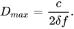
The unambiguous range measurement interval for single-frequency probing is determined by the expression:

where  — the speed of light;
 — the radiated frequency.
To extend the unambiguous range measurement interval, more complex schemes with two or more frequencies are used in practice. In this case the unambiguous range is determined by the maximum frequency separation  of the radiated signals:
Advantages:
Disadvantages:
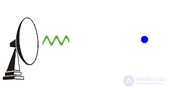
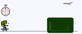
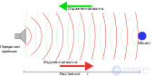
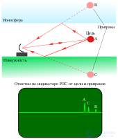
Operating principle of a pulse radar
|
|
|
|
Modern tracking radars are usually built as pulse radars. A pulse radar transmits the radiated signal only for a very short time, as a short pulse (duration on the order of microseconds), and then switches to receive mode and listens for the echo reflected from the target while the radiated pulse propagates through space.
Since the pulse travels away from the radar at a constant speed, there is a direct relationship between the time elapsed from sending the pulse to receiving the echo and the range to the target. It makes sense to send the next pulse only after some time, namely after the previous pulse has come back (this depends on the radar detection range, transmitter power, antenna gain and receiver sensitivity). If a pulse is sent earlier, the echo of the previous pulse from a distant target may be mistaken for the echo of the second pulse from a nearby target.
The time interval between pulses is called the pulse repetition interval (PRI); its reciprocal is an important parameter called the pulse repetition frequency (PRF). Low-frequency long-range surveillance radars typically have a repetition rate of several hundred pulses per second. The pulse repetition frequency is one of the distinguishing features by which the radar model can be determined remotely.
Advantages of the pulse method of range measurement:
Disadvantages:
|
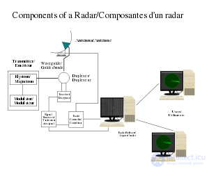
Simplified radar block diagram
|
One of the main problems of pulse radars is suppressing signals reflected from stationary objects: the Earth's surface, high hills, wave crests, etc. If, for example, a target is against the background of a high hill, the signal reflected from that hill will completely mask the signal from the target. For ground-based radars this problem appears when working with low-flying objects. For airborne pulse radars it shows up in that reflections from the Earth's surface obscure all objects lying below the aircraft carrying the radar.
Clutter suppression methods use the Doppler effect in one way or another (the frequency of a wave reflected from an approaching object increases, and from a receding object decreases).
The simplest radar that can detect a target in clutter is the moving target indication (MTI) radar — a pulse radar that compares reflections from two or more pulse repetition intervals. Any target that moves relative to the radar produces a change in a signal parameter (the phase in a coherent MTI), whereas clutter from stationary objects remains unchanged. Clutter suppression is achieved by subtracting the reflected signals received in two successive intervals. In practice, clutter suppression can be implemented in dedicated devices — delay-line (pulse-to-pulse) cancelers — or by software processing in a digital system.
An inherent drawback of MTI radars operating with a constant PRF is the inability to detect targets with specific tangential velocities (targets that produce a phase change of exactly 360 degrees). The velocity at which a target becomes invisible to the radar depends on the operating frequency of the station and on the PRF. To eliminate this drawback, modern MTI radars emit several pulses with different PRFs. The PRFs are selected so that the number of "blind" speeds is minimal.
Pulse-Doppler radars, unlike MTI radars, use a different, more complex method of clutter rejection. The received signal, containing information about targets and clutter, is fed to the input of a Doppler filter bank. Each filter passes a signal of a certain frequency. At the filter outputs, derivatives of the signals are computed. The method helps to find targets with given velocities, can be implemented in hardware or software, and does not (without modifications) allow determination of target ranges. To determine target ranges, the pulse repetition interval can be divided into segments (called range gates), and the signal is fed to the input of the Doppler filter bank during a given range gate. The range can be computed only with multiple pulse repetitions at different frequencies (the target appears in different range gates at different PRFs).
An important property of pulse-Doppler radars is signal coherence — the phase relationship between the transmitted and received (reflected) signals.
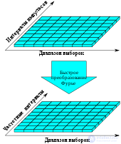
Pulse-Doppler radars, unlike MTI radars, are more successful at detecting low-flying targets. On modern fighters these radars are used for air intercept and fire control (AN/APG-63, 65, 66, 67 and 70 radars). Modern implementations are mostly software-based: the signal is digitized and passed to a separate processor for processing. The digital signal is often converted, using the fast Fourier transform, into a form convenient for other algorithms. A software implementation has a number of advantages over a hardware one:
The listed advantages, along with the ability to store data in ROM), make it possible, when necessary, to adapt quickly to the enemy's jamming techniques.
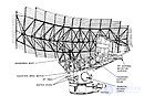
The most effective method of countering active jamming is to use a digital antenna array in the radar, which makes it possible to form nulls in the radiation pattern in the directions of the jammers
|
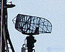
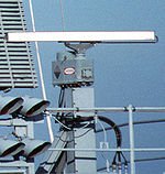
Surveillance radar antenna
|
Secondary radar is used in aviation for identification. Its main feature is the use of an active transponder on aircraft.
The operating principle of a secondary radar differs somewhat from that of a primary radar. A secondary surveillance radar station is built around the following components: a transmitter, an antenna, azimuth pulse generators, a receiver, a signal processor, an indicator, and an aircraft transponder with an antenna.
Transmitter is used to generate the interrogation pulses in the antenna at a frequency of 1030 MHz.
|

|
|
Antenna is used to transmit the interrogation pulses and receive the reflected signal. Under ICAO standards for secondary radar, the antenna transmits at a frequency of 1030 MHz and receives at a frequency of 1090 MHz.
Azimuth pulse generators are used to generate azimuth change pulses (Azimuth Change Pulse, ACP) and the north mark (Azimuth Reference Pulse, ARP). For each revolution of the radar antenna, 4096 azimuth change pulses (for older systems) or 16,384 improved azimuth change pulses (Improved Azimuth Change Pulse, IACP — for newer systems) are generated, as well as one north mark. The north mark is delivered by the azimuth pulse generator when the antenna is pointing North, while the azimuth change pulses are used to measure the angle of rotation of the antenna.
Receiver is used to receive the pulses at a frequency of 1090 MHz.
Signal processor is used to process the received signals.
Indicator is used to display the processed information.
Aircraft transponder with antenna is used to transmit a pulsed radio signal containing additional information back toward the radar when interrogated.
The operating principle of a secondary radar is to use the energy of the aircraft transponder to determine the position of the aircraft. The radar illuminates the surrounding space with interrogation pulses P1 and P3, and with a suppression pulse P2, at a frequency of 1030 MHz. Aircraft equipped with transponders that are within the coverage of the interrogation beam, upon receiving the interrogation pulses, provided that the condition P1,P3>P2 holds, reply to the interrogating radar with a series of coded pulses at a frequency of 1090 MHz, which contain additional information such as the aircraft's identification number, altitude, and so on. The response of the aircraft transponder depends on the interrogation mode of the radar, and the interrogation mode is determined by the time interval between the interrogation pulses P1 and P3. For example, in interrogation mode A (mode A), the time interval between the station's interrogation pulses P1 and P3 is 8 microseconds, and upon receiving such an interrogation the aircraft transponder encodes its identification number in the reply pulses.
In interrogation mode C (mode C), the time interval between the station's interrogation pulses is 21 microseconds, and upon receiving such an interrogation the aircraft transponder encodes its altitude in the reply pulses. The radar can also send interrogations in a mixed mode, for example, Mode A, Mode C, Mode A, Mode C. The azimuth of the aircraft is determined by the antenna rotation angle, which in turn is determined by counting the azimuth change pulses.
Range is determined from the delay of the received reply. If the aircraft is within the coverage of the sidelobes rather than the main beam, or is behind the antenna, then upon receiving an interrogation from the radar the aircraft transponder will find at its input the condition that the pulses P1,P3
The signal received from the transponder is processed by the radar receiver and then goes to the signal processor, which processes the signals and delivers the information to the end user and/or to a monitoring indicator.
Advantages of secondary radar:
| Designation IEEE / ITU |
Etymology | Frequencies | Wavelength | Notes |
|---|---|---|---|---|
| HF | Eng. high frequency | 3—30 MHz | 10—100 m | Coast guard radars, "over-the-horizon" radars |
| P | Eng. previous | < 300 MHz | > 1 m | Used in the first radars |
| VHF | Eng. very high frequency | 50—330 MHz | 0.9—6 m | Long-range detection, Earth observation |
| UHF | Eng. ultra high frequency | 300—1000 MHz | 0.3—1 m | Long-range detection (for example, of artillery fire), studies of forests and the Earth's surface |
| L | Eng. long | 1—2 GHz | 15—30 cm | air traffic surveillance and control |
| S | Eng. short | 2—4 GHz | 7.5—15 cm | air traffic control, meteorology, marine radars |
| C | Eng. compromise | 4—8 GHz | 3.75—7.5 cm | meteorology, satellite broadcasting, intermediate band between X and S |
| X | 8—12 GHz | 2.5—3.75 cm | weapon control, missile guidance, marine radars, weather, medium-resolution mapping; in the USA the 10.525 GHz ± 25 MHz band is used in airport radars | |
| Ku | Eng. under K | 12—18 GHz | 1.67—2.5 cm | high-resolution mapping, satellite altimetry |
| K | Ger. kurz — "short" | 18—27 GHz | 1.11—1.67 cm | use is limited because of strong absorption by water vapor, so the Ku and Ka bands are used instead. The K band is used for cloud detection and in police traffic radars (24.150 ± 0.100 GHz). |
| Ka | Eng. above K | 27—40 GHz | 0.75—1.11 cm | Mapping, short-range air traffic control, special radars that control traffic enforcement cameras (34.300 ± 0.100 GHz) |
| mm | 40—300 GHz | 1—7.5 mm | millimeter waves, divided into the following two bands | |
| V | 40—75 GHz | 4.0—7.5 mm | medical EHF devices used for physiotherapy | |
| W | 75—110 GHz | 2.7—4.0 mm | sensors in experimental autonomous vehicles, high-precision studies of weather phenomena |
| Designation | Frequencies, MHz | Wavelength, cm | Examples |
|---|---|---|---|
| A | < 100—250 | 120 — >300 | Early warning and air traffic control radars, e.g. the 1L13 "NEBO-SV" radar |
| B | 250 — 500 | 60 — 120 | |
| C | 500 −1 000 | 30 — 60 | |
| D | 1 000 — 2 000 | 15 — 30 | |
| E | 2 000 — 3 000 | 10 — 15 | |
| F | 3 000 — 4 000 | 7.5 — 10 | |
| G | 4 000 — 6 000 | 5 — 7.5 | |
| H | 6 000 — 8 000 | 3.75 — 5.00 | |
| I | 8 000 — 10 000 | 3.00 — 3.75 | Airborne multifunction radars |
| J | 10 000 — 20 000 | 1.50 — 3.00 | Target tracking and illumination radars (TIR), e.g. 30N6, 9S32 |
| K | 20 000 — 40 000 | 0.75 — 1.50 | |
| L | 40 000 — 60 000 | 0.50 — 0.75 | |
| M | 60 000—100 000 | 0.30 — 0.50 |

Comments