
Lecture 14 min.
The goal of this lecture is to become familiar with the antennas most often used in practice. These are the classes of simple and complex reflector antennas, as well as slot and stripline antennas. A wide variety of antennas are used in radars. The goal of the lecture is to teach the student to understand the design of different antennas.
Outline
When choosing an antenna for a radar, several factors should be taken into account.
Here are some of them:
Operating frequency: Determine the required operating frequency of the radar, since it will affect the choice of antenna type. Some antennas are designed to operate at specific frequencies, and the choice must match the required operating frequency.
Directivity: Determine whether you need a directional or an omnidirectional antenna. Directional antennas provide narrower coverage and higher accuracy, but require precise pointing to detect targets. Omnidirectional antennas provide wide coverage, but with lower accuracy.
Gain: Antenna gain is important for ensuring sufficient radar sensitivity. Higher antenna gain provides a longer detection range and better resolution.
Size and shape: The size and shape of the antenna may be limited by the physical constraints of the installation. For example, a portable radar may require a compact antenna, whereas larger antennas can be used for a ground-based installation.
Polarization: The choice of antenna polarization depends on the operating environment and the radar requirements. Horizontal, vertical or circular polarization may be chosen depending on the circumstances.
Ease of installation and adjustment: Pay attention to how easy the antenna is to install and adjust. It is important to choose an antenna that can be easily installed and tuned for optimal radar performance.
Cost: Finally, consider budget constraints. There is a wide range of antennas at different prices, and you should choose an antenna that fits your budget without sacrificing quality and performance.
These are only a few of the key factors to consider when choosing an antenna for a radar. It is important to carry out a more detailed study, evaluating the requirements of your specific radar and consulting experts in the field for more accurate recommendations.
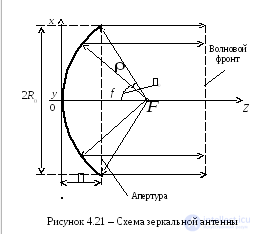
Reflector antennas belong to the class of parabolic antennas. They consist of a main reflector in the shape of a paraboloid and a feed device (often called a feed), located at the focus of the parabola. The main reflector reflects the incident electromagnetic waves from the feed and forms a narrow transmit or receive beam.
Reflector antennas have a number of advantages that make them popular in various fields:
High directivity: Reflector antennas provide a highly directive transmit or receive beam. This allows them to detect or transmit signals in a narrow direction, increasing the accuracy and range of communication.
High gain: The parabolic shape of the main reflector allows the antenna to have high gain. The gain is determined by the size and shape of the paraboloid, and it is proportional to the antenna diameter. Large reflector antennas provide higher gain.
Wide frequency range: Reflector antennas can be used over a wide frequency range, from radio frequencies to microwaves and even in the optical range.
Minimal losses: Owing to the reflective nature of reflector antennas, they have low signal losses, which contributes to high efficiency and quality of communication or reception.
Use in various applications: Reflector antennas are widely used in radio communications, satellite communications, radars, television, radiolocation and other fields where high directivity and signal gain are required.
However, it should be noted that reflector antennas also have some limitations, including large size and weight for high-gain antennas, as well as a limited field of view associated with their directional nature. These factors must be taken into account when choosing a reflector antenna for a specific application.
High radiation directivity can be obtained, besides with antenna arrays, with antennas such as horn antennas, reflector antennas, and others. A characteristic feature of these antennas is the presence of a radiating aperture, i.e. some surface through which the energy is radiated.
Reflector antennas are used in various frequency ranges: from optical to short-wave, and especially widely in the centimeter, decimeter and millimeter bands. These antennas are distinguished by their design simplicity, the possibility of obtaining various radiation patterns, good bandwidth properties, and so on.
There are various types of reflector antennas: parabolic reflectors (paraboloid, truncated paraboloid and parabolic cylinder); spherical reflectors, flat and corner reflectors, and others.
The type of antenna for a radar is chosen on the basis of a number of considerations. Sometimes they are contradictory.
In the radar equation, the power of the reflected signal grows in proportion to the square of the product of the antenna gain and the wavelength Ga2λ2. To achieve a given range R, it is advantageous to use an antenna that is as large as possible. A large antenna aperture makes it possible to obtain a high gain Ga and thereby reduce the transmitter power. For example, doubling Ga allows the transmitter power to be reduced by a factor of four (see the radar equation).
On the other hand, the large dimensions of an antenna may not fit within the permissible dimensions of the station. Engineers have to revise their decisions more than once until an acceptable option is found.
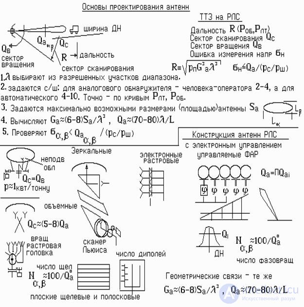
At the beginning of radar design, the approach to antenna selection can follow the scheme given in the figure. This is the technical proposal stage. The main task of this stage is not an exact calculation but an approximate one. It is what makes it possible to reconcile conflicting requirements without a significant expenditure of time. What antennas are used in radars of different classes?
Used exclusively in inexpensive consumer radars. These are radars of roadside patrol services and intruder alarm systems.
The class of "flat" antennas belongs to the group of antennas with flat or nearly flat radiating elements. They differ from traditional three-dimensional antennas, such as reflector antennas or dipole antennas, and have a number of unique properties and advantages. Here are several examples of classes of flat antennas:
Planar aperture antennas (Planar Aperture Antennas): These are antennas with a flat radiating element, usually made in the form of a flat surface with holes or slots. They can provide a wide field of view and a good rectangular radiation pattern. Examples are microstrip antennas and grid antennas.
Phased arrays (Phased Arrays): Phased arrays consist of a number of flat radiating elements that work together to form radiation beams by varying the phase and amplitude of the signal at each element. This makes it possible to steer the beam direction electronically without the need to physically rotate the antenna. Phased arrays are widely used in radars, communication systems and satellite communications.
Metamaterials (Metamaterial Antennas): Metamaterials are artificial structures made of metallic or dielectric elements specially designed to manipulate electromagnetic waves. Flat antennas based on metamaterials can have unique properties, such as a low profile, wide bandwidth and the possibility of realizing unusual radiation patterns.
Flat antennas generally have a number of advantages, including compactness, light weight, ease of installation and aesthetic appeal. They can be used in various applications such as wireless communications, radiolocation, medical diagnostics, automotive electronics and much more. However, as with any antenna, the choice of a flat antenna should be based on the requirements of the specific application and the environmental conditions.
Used in radars with slow space scanning, for example 4-10 degrees per second. The Russian-made PSN-1 and PSNR-5 radars are equipped with such antennas. Their main advantage is ease of manufacture, and their drawback is the considerable amount of space they occupy because of the offset feed. Fast space scanning requires high electric drive power, since scanning is performed by rotating the entire antenna assembly. Rotating the assembly requires motors with a power of 5-10 kW per 1 tonne of mass. If fast rotation is not required, one kilowatt is sufficient.
However, because of their ease of manufacture, these antennas are quite widely used in airfield radars and air defense radars.
For narrow sectors (5-10 deg.), mechanical movement of the feed horn in the focal plane is used. In this way the beam can be moved over 5-8 beamwidths.
If N horns are placed in the focal plane and fed in turn, the pattern can be made to scan fairly quickly. For convenience, the waveguides from each horn are joined into a ring. The resulting structure is called a "raster head". A waveguide rotates inside the ring of the horn head. It is the one that performs the scanning.
To widen the scan sector Qc, the Lewis scanner is often used. It is characterized by the use of a narrow metal mirror placed at 90 deg. to the focal plane. The structure forms a waveguide "gusset". Here the feed horn can be moved not along the focal plane but across it. And if this "gusset" is rolled up into a "spiral" forming an annular slot, the feed horn can be rotated. This design makes it possible to extend the scan sector of the antenna pattern to 50 beamwidths. This type of antenna is used in the SNAR radar.
The relative bulkiness of reflector antennas has prevented their use in man-portable radars and in the seekers of guided missiles. Slot and stripline antennas are more compact.
Slot antennas have the form of a flat sheet of waveguides. Radiating slots are cut in each waveguide. They form the pattern in the horizontal plane. The vertical plane pattern is determined by the number of waveguides in the vertical direction.
The waveguides are fed by a waveguide power divider. To make the antenna lighter, the waveguides are made of plastic with subsequent metal deposition. Often the waveguide and distribution parts are cast from plastic in one piece and covered with a common slotted aluminum sheet.
Stripline antennas are the cheapest. A pattern of dipoles with a feed line is applied to foil-clad Teflon. The Teflon is then etched. The remaining stripline-dipole structure forms the antenna pattern. It is covered with a rectangular metal or metallized cavity resonator. The antenna turns out flat and compact. Such an antenna is used in the SBR-3 radar. Space scanning is performed by rotating the entire structure.
Solving a number of tasks requires very fast (less than 1 millisecond) switching of the beam from one point in space to another. For example, in multichannel tracking of many targets. These are air defense tasks and locating firing positions from the shot. This cannot be done mechanically. Electronically steered systems have been developed for this purpose. NxM radiators in the form of dipoles or miniature horns with electronic phase shifters (PS) are placed on a flat surface. Each phase shifter can change the phase of the signal radiated into space. Using a computer, one can calculate the phase state of each phase shifter that will provide the required beam direction. Each phase shifter receives a phase-setting command from the computer, and in this way a phase front is formed in the antenna aperture.
The switching time of electronic phase shifters can be 10-50 μs.
Phase shifters and the control system are very expensive elements. A single phase shifter can cost up to $100. As shown in the figure, to provide an antenna pattern in only one plane, N=101 / Qa phase shifters are needed. To form a 2° × 2° antenna pattern in two planes
50×50 = 2500 units will be required. Taking into account the price of one PS, the total cost of one array can be $250,000.
Phased array antennas (PAAs) have a wide range of applications in various fields. Here are some of them:
Radiolocation: Phased arrays are widely used in radar systems for detecting, tracking and measuring objects in the air, at sea and on land. They provide electronic scanning of the radiation beam without the need to physically rotate the antenna, which makes them ideal for radar systems with a high update rate and accuracy.
Satellite communications: Phased arrays are widely used in satellite communication systems for transmitting and receiving signals. They make it possible to efficiently form narrow beams in the direction of the satellite, providing high throughput and communication quality.
Wireless communications: Phased arrays are used in cellular networks and wireless communication systems to increase throughput and service area coverage. They make it possible to efficiently control the direction of the beams, providing more stable communication and increased network capacity.
Aerospace industry: Phased arrays are used in the aerospace industry for communication, navigation and radiolocation on board aircraft, satellites and spacecraft. They provide high accuracy and reliability of communication in difficult conditions.
Medical diagnostics: Phased arrays are used in medical diagnostics, for example in ultrasound imaging systems, for focusing and forming the beam of ultrasonic waves.
Military systems: Phased arrays are widely used in military systems, including radar detection, target designation and defense systems. They provide high accuracy and stealth during operation.
Automotive electronics: Phased arrays can be used in automotive electronics, including autopilot and parking assistance systems. They help in detecting obstacles and determining the distance and direction of movement.
These are only some of the many areas of application of phased arrays. Their ability to scan electronically and to control the radiation direction precisely makes them a versatile tool for many applications where high directivity and antenna system efficiency are required.
1. Is it advantageous to increase the antenna gain, and why?
2. How is space scanning organized by an antenna?
3. How does the Lewis scanner work?
4. What are phased arrays needed for, and how do they work?

Comments