
Lecture 10 min.
Antenna design is the process of developing and optimizing an antenna system for a specific application or task. Below are the main steps and principles that are usually taken into account when designing antennas:
Defining requirements: The first step is to define the requirements and goals of the project. This includes the tasks the antenna must perform, such as frequency range, directivity, gain, bandwidth, etc. Physical constraints, such as available space and budget, are also taken into account.
Research and analysis: In this step, different types of antennas, technologies, and configurations that are best suited to the given requirements are researched and analyzed. It is important to study and evaluate their advantages, limitations, radiation characteristics, and other factors.
Selecting the antenna configuration: Based on the results of the analysis, the most suitable antenna configuration is selected. The options may include dipole antennas, reflector antennas, aperture antennas, phased arrays, and others, depending on the requirements and the application.
Modeling and simulation: To optimize the antenna system, modeling and simulation are performed using specialized software. This makes it possible to analyze and evaluate the electromagnetic characteristics of the antenna, such as radiation patterns, gain, frequency response, etc.
Optimization: Based on the modeling and simulation results, the antenna system is optimized. This may include changing the antenna geometry, selecting materials, and optimizing dimensions and parameters in order to achieve the required characteristics.
Prototyping and testing: After optimization, a prototype of the antenna is built. Experimental measurements and testing are then carried out to verify and compare the simulation results. This makes it possible to introduce additional adjustments and improvements to the design.
Production and deployment: After the antenna has been successfully designed and tested, one can proceed to manufacture it on a large scale and deploy it in the system or device for which it is intended.
Antenna design is a complex and multifaceted process that requires knowledge of electromagnetics, radio engineering, and mathematical modeling. Effective antenna design requires a balance between the application requirements, physical constraints, and the electromagnetic characteristics of the antenna.
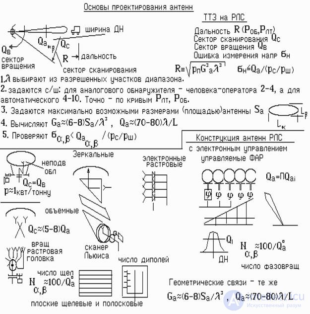
The type of radar antenna is chosen on the basis of a number of considerations, which are sometimes contradictory.
The wide range of wavelengths radiated (received) by antennas (from tens of kilometers to fractions of a millimeter) and the diversity of antenna applications (radio communications, television, radar, radio astronomy, meteorology, medicine, etc.) have given rise to a large number of antenna types and designs (Fig. 2). At long, medium, and short waves, the antennas mainly used are symmetric and asymmetric dipoles, Yagi ("wave channel") antennas, phased antenna arrays, log-periodic antennas, and loop antennas (the latter are often fitted with a magnetic core to increase efficiency; see Magnetic antenna). For receiving and transmitting radio waves in the microwave range, horn, lens, slot, dielectric, and reflector antennas are the most widely used.
A distinction is made between so-called passive antennas (containing no amplifying elements) and active antennas. Passive antennas are reciprocal (they can operate in both transmit and receive modes) and are widely used in various low-power transceiver devices. An increase in the power of radio transmitters requires higher electrical strength of antenna components, while an increase in the sensitivity of radio receivers requires reduced thermal noise and a miniaturized design; moreover, an antenna for transmission and reception often must have different radiation patterns. The impossibility of combining these requirements in one type of antenna has made it necessary to develop and use separate transmitting and receiving antennas. For example, a television transmitting antenna has a circular radiation pattern in the horizontal plane, i.e., it is an omnidirectional antenna, whereas a television receiving antenna must be directional (except for a car antenna) in order to avoid receiving possible interference, including transmissions from other television centers, as well as signals of the desired program reflected from various obstacles, which cause ghosting (multipath images) on the television screen.
The shape of the radiation pattern is very important. For example, low-directivity antennas with a wide radiation pattern are used as onboard antennas of aircraft. Antennas of radar systems intended for surveillance of space and rotating about a vertical axis have a narrow radiation pattern in the horizontal plane and a wide one in the vertical plane, or one consisting of many narrow beams scanning the space. Radio astronomy antennas and antennas of space communication systems must have extremely high directivity (a pencil-beam pattern) for accurate determination of the position of an object.
The design of antennas is determined mainly by their purpose and operating frequency range. Thus, antennas for long and medium waves are usually tower masts (200–400 m high) carrying a branched wire array; in combination with super-powerful (over 1 MW) radio transmitters, they provide communication all over the globe, including with submarines at depths of up to several hundred meters. In the VHF range, parabolic antennas are widely used, consisting of a metal reflector in the form of a paraboloid with a feed placed at its focus. Such antennas are used in radio telescopes, satellite television systems, and others. Underground antennas are mostly wire systems buried in trenches. Satellite communication antennas (e.g., umbrellas that unfold when placed into orbit, parabolic reflectors of ground communication stations) are distinguished by particular complexity and manufacturing precision, as are radio astronomy antenna systems intended for receiving radio signals from other galaxies, radar observation of celestial bodies, and measuring cosmic distances.
A characteristic feature of the development of modern antenna technology is the use of antennas with signal processing (digital, analog, space-time, coherent and incoherent optics methods, etc.). Such antennas include phased antenna arrays with computer-controlled radiation patterns and radio astronomy aperture synthesis systems. Global ground-based and space-based aperture synthesis systems linked via artificial Earth satellites are promising. Modern methods of antenna analysis and synthesis make it possible to select their geometry with high accuracy and to model electromagnetic fields in the far field, corresponding to the classical applications of radio communication and radar systems.
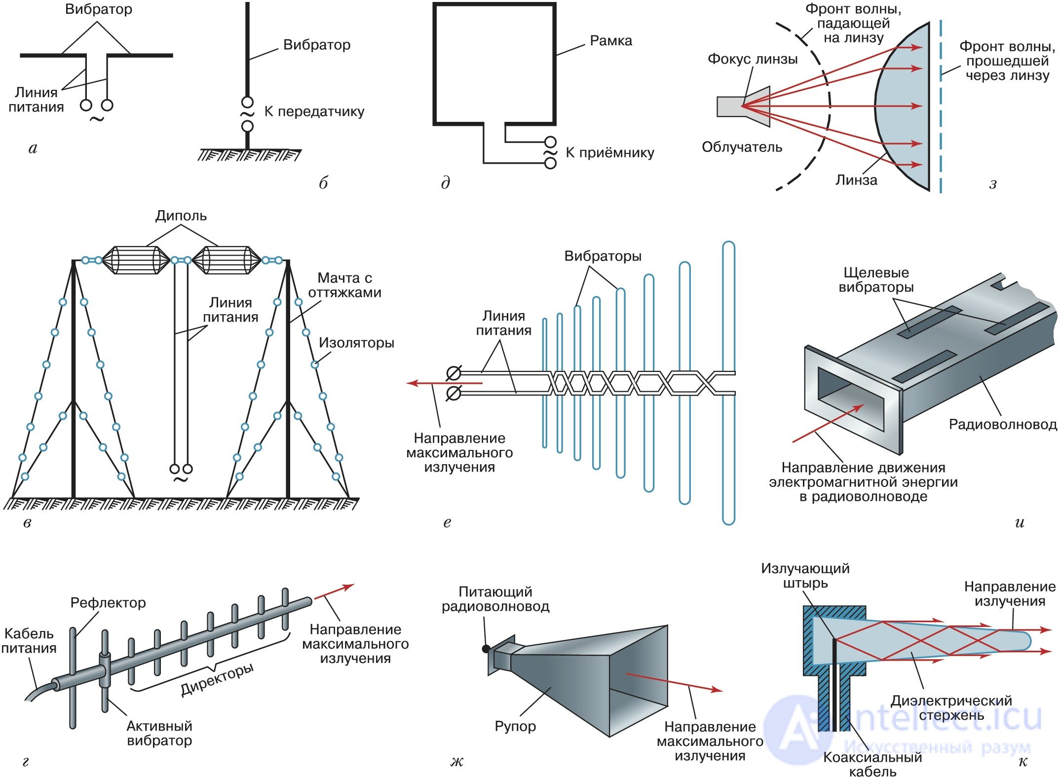
Fig. 2. Types of antennas: symmetric (a) and asymmetric (b) dipoles; Nadenenko dipole (c); Yagi ("wave channel") (d); loop (e); log-periodic dipole array (f); horn (g); lens (h); waveguide slot (i); dielectric (j).
Basic concepts of electrodynamics and the theory of the electromagnetic field:
Electrodynamics: Electrodynamics is the branch of physics that studies the interaction of charged particles with the electromagnetic field. It includes Maxwell's laws, which describe electric and magnetic fields and their interaction with charges and currents.
Electromagnetic field: The electromagnetic field is a physical field formed by electric and magnetic components that interact with each other and propagate in space in the form of electromagnetic waves.
Projection methods for solving electrodynamic problems:
Projection methods are numerical methods for solving the equations of electrodynamics that are based on representing fields as projections onto some functional basis, such as basis functions.
Finite Difference Method (FDM): The finite difference method is based on approximating the derivatives in the equations of electrodynamics by difference quotients. The equations are transformed into a system of linear algebraic equations, which is solved numerically on a grid consisting of nodes.
Finite Element Method (FEM): The finite element method divides the domain into a set of small subdomains called finite elements. The fields in each element are approximated using basis functions, and the equations of electrodynamics are solved numerically on the basis of these approximations.
Integral Equation Method (IEM): The integral equation method is based on representing fields in the form of integral equations. In this case, the equations of electrodynamics are transformed into integral equations, which are solved numerically.
Theoretical foundations of the MWO program:
MWO (Microwave Office) is software for designing and simulating microwave and radio-frequency systems. It is based on the numerical solution of Maxwell's equations and other techniques for modeling electromagnetic fields. The MWO program makes it possible to create and analyze microwave components and devices, such as antennas, filters, amplifiers, and others.
Theoretical foundations of the HFSS program:
HFSS (High-Frequency Structure Simulator) is software for modeling and analyzing electromagnetic fields in the microwave and radio-frequency ranges. It uses the finite element method for the numerical solution of Maxwell's equations and makes it possible to model and analyze complex structures, including antennas, filters, waveguides, and microstrip lines.
Theory of wire antennas:
The theory of wire antennas studies the properties and characteristics of antennas consisting of wire elements or wire structures. Wire antennas have a simple design and a wide range of applications. They can be made from straight wires, circular loops, helices, and other wire shapes.
Theory of microstrip antennas:
The theory of microstrip antennas studies the properties and characteristics of antennas that use microstrip lines. Microstrip antennas have a compact size, a low profile, and wide tuning capabilities. They are used in mobile communications, radar, satellite communication systems, and other applications where miniaturization and efficient operation in the microwave range are required.
Software is often used in the design process
HFSS offers the following modeling methods and tools, depending on the type of problem to be solved:
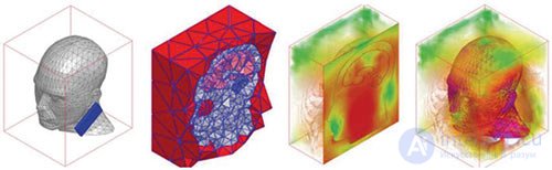
Fig. 3. Example of solving a problem using the finite element method

Fig. 4. Change in the antenna radiation pattern
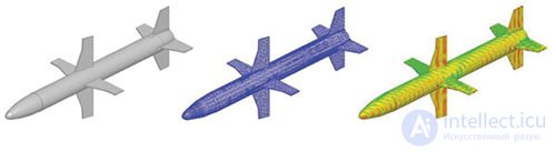
Fig. 5. Integral equation method: (a) missile geometry;
(b) surface mesh; (c) current distribution over the surface
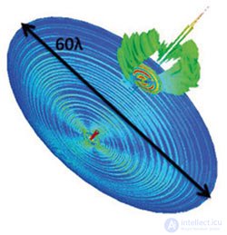
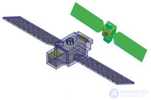
Fig. 6. Use of the hybrid method: (a) reflector antenna; (b) antenna on a satellite with conformal boundary conditions
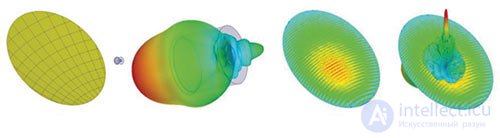
Fig. 7. Modeling a reflector antenna using physical optics: (a) geometry of the reflector and feed (horn); (b) electric field surrounding the horn; (c) current distribution over the reflector surface; (d) far-field pattern superimposed on the reflector with the current distribution
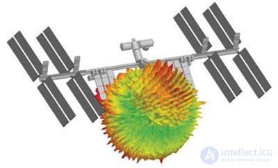
Fig. 8. The radiation pattern of an antenna mounted on the International Space Station is shown. The PO method is used
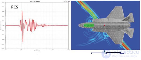
Fig. 9. HFSS-Transient solver: (a) time-domain RCS signature;
(b) snapshot of the electromagnetic fields at a given instant of time
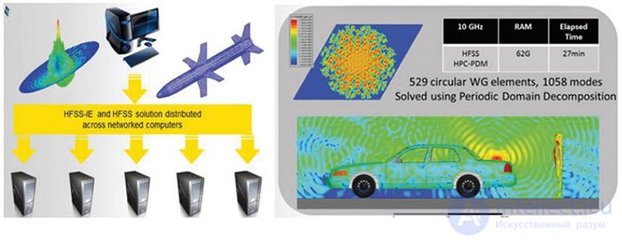
Fig. 10. DDM (domain decomposition method): (a) concept;
(b) examples
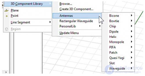
Fig. 11. Antenna type selection menu
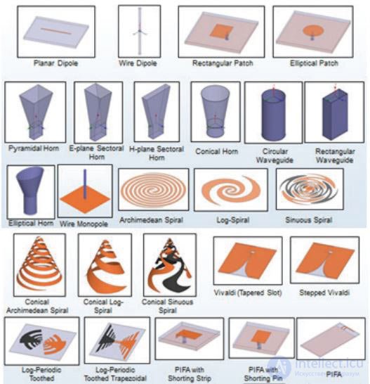
Fig. 12. Some of the antenna types available in the ADK toolkit

Comments