Lecture
Это окончание невероятной информации про схемотехника цифровых узлов.
...
the waiting vertex, the exit from it is possible only if condition X is met.
The microprogram graph consists of a set of listed vertices and arcs connecting the outputs of some vertices with the inputs of others. The connection of the vertices and the direction of the arcs of the graph is determined on the basis of the algorithm of the operation described by the graph and the structure of the operational machine.
The firmware itself and its graph must be correct, i.e. meet the following conditions:
1. in the column there should be only one initial and one final vertex;
2. at any vertex of the graph must lead at least one path from the initial vertex;
3. from each exit of any vertex of the graph there must be at least one path to the final vertex;
4. for all possible values of logical conditions and used words, there must be a path from the initial vertex to the final one.
An example of a GSA is presented in Figures 5.11 and 5.12.
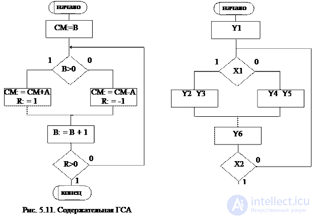
GAW presented in fig. 5.11, is called meaningful , because inside vertices, micro-operations and logical conditions are written explicitly. If each micro-operation is denoted by the symbols Yi, a logical conditions through Xi, then we get the so-called coded GSA (Fig. 5.12). For the correct perception of the firmware specified in the form of a coded GSA, it is necessary to know the correspondence between Yi, Xi and the content of the corresponding micro-operations and logical conditions.
There is a strict interrelation between the graph - the scheme of the operational device and the transition graph controlling the operation of this operational device. In fig. 5.13.a shows the GSA of some operational device, the firmware of which is executed under the initial condition H = 1. The conditions specified in this GSA, determine the sequence of micro-operations. Let's see how to associate a firmware graph diagram with a Moore or Mili machine gun.
For Moore’s automaton, the output signal depends only on its internal state, i.e. in our case, V = F (Q) . Therefore, each operator vertex of the GSA should be marked with the symbol of the initial state of the automaton q i . In fig. 5.13.a to the left of the operators, a GSA mark was given, interpreted as Moore’s automaton. These marks are used to build the transition graph of the Moore automaton (Fig. 5.13.b), where the vertices are the states of the automaton, and the arcs are the conditions for transitions from one state to another. Thus, the functions of the outputs of the machine Moore  , where q i is the state of the automaton, ensuring the generation of the signal v i .
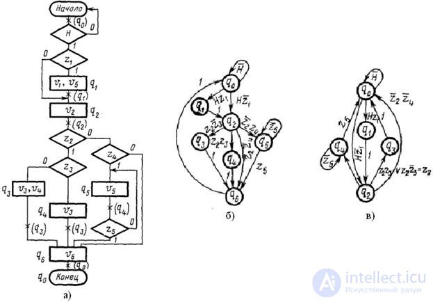
Fig. 5.13. GSA operational device (a) and Moore (b) and Mile (c) automatic transition graphs
The transition of an automaton from one state to another in the absence of logical conditions (unconditional transition) occurs under the action of a clock signal. The conditional transition occurs in the direction that corresponds to the computed value of the condition z i .
To build an Mile machine, remember that the output signal depends on both the internal state and the input signal.
The GSA marking of the Mile machine gun is done differently than for the Moore machine gun . The symbol q 0 marks the entrance of the first vertex of the graph, following the initial one, and the input of the final vertex of the GSA. The outputs of the other operator vertices are denoted by the symbol q i . In fig. 5.13.a states of the automatic machine Miles are marked with the symbols q 0 ÷ q 4 , taken in brackets. The transition graph of the Mile machine is shown in Fig. 5.13.in. In Mil machines, the functions of the outputs for which micro-operations signals are generated are determined by the formula  , where q i is the state of the automaton, accompanied by the generation of the signal v j , z k is the logical condition that determines the generation of the signal when the automaton passes from the state q i .
In the case of an unconditional transfer of the automaton from the state q i, the signal v j is determined only by the value q i .
In the future, we will consider the synthesis of only UA and only encoded GAW.
A finite state machine interpreting the firmware of a discrete device is called a firmware automaton. The same GSA can be interpreted as a Miles machine gun and a Moore machine gun.
Abstract synthesis of the firmware of the GSA machine is carried out in two stages :
1. Getting marked GSA;
2. Construction of the graph of the automaton or tables of transitions and exits.
At the stage of obtaining the marked GSA, the inputs of the vertices following the operator ones are marked with the symbols a 1 , a 2 , .. according to the following rules:
- the symbol a 1 marks the input of the vertex following the initial one, as well as the input of the final vertex;
- the inputs of all vertices following the operator should be marked;
- the inputs of different vertices, with the exception of the final one, are marked with different symbols;
- if the vertex entry is marked, then only one symbol.
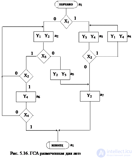
It is clear that for the marking will require a finite number of characters a 1 , ..., a m . The result of the first stage is the noted GSA, which serves as the basis for the second stage - the transition to a graph or transition-output tables. An example of the GSA, marked for the Miles, is shown in Fig. 5.14.
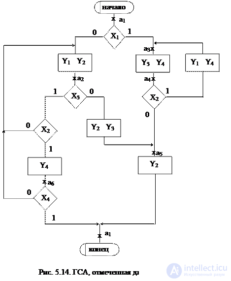
At the second stage, an automaton graph or a transition-output table is constructed from the noted GSA. For this, it is assumed that the automaton will have as many states as the symbols a i needed at the GSA mark.
On the plane of the figure, we mark all the states of the automaton a i . For each of the states a i, we determine by the marked GSA all paths leading to other states and passing necessarily through only one operator vertex . For example, from the state а 1 (Fig.5.14.) There is a transition to the state a 2 (the path passes through the operator vertex y 1 y 2 ) and to the state a 4 (the path passes through the vertex y 3 y 4 ). There is no transition from a 1 to a 3 , since there are no operator vertices on this path. We assume that the automaton performs the transition, for example, from a 1 to a 2 under the condition x 1 = 0 and generates output signals y 1 2 at this transition (what is written in the GSA operator vertex passed, Fig. 5.14). The value of the conditions x 2 , x 3 , x 4 at this transition does not affect the automaton.
 The only exception is the path leading to the final vertex, it may not contain any operator vertices (for example, the transition from a 6 to a 1 ), i.e. not accompanied by the generation of output signals.
We mark on the graph all the indicated paths for all states in the form of arcs, to which we attribute the transition conditions and the output signal generated at this transition. We obtain the graph of the Mile automaton (Fig. 5.15).
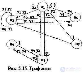
On this graph, transition condition of type а 3 ®a 4 , a 5 ®a 1 is attributed to transition condition 1, since these transitions are unconditional and are always performed when the automaton enters the state a 3 or a 5 . Based on the noted GSA or graph of the automaton, it is possible to build a table of transitions-outputs. For automata automata, the transition-output table is constructed in the form of a list and the forward and reverse tables are distinguished. For this machine, the direct table is presented in table. 5.11, reverse - in table. 5.12.
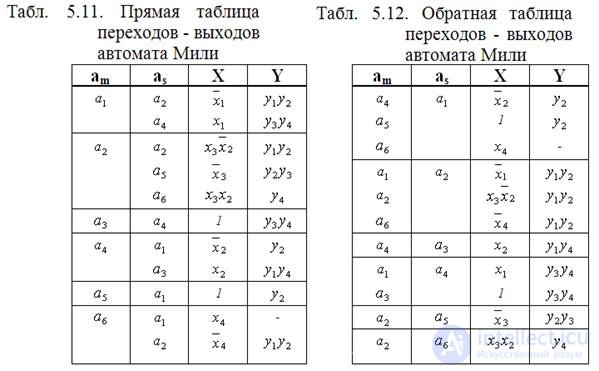
In the above tables, a m is the initial state, a s is the transition state, X is a condition (input signal) that provides a transition from the a m state to the a s state, Y is the output signal produced by the automaton upon the transition from a m to a s .
The difference between the direct transition table and the output from the inverse is that in the direct table the records are grouped by states a m , and in the reverse table - by states a s .
For Moore’s automaton, at the stage of obtaining the noted GSA, markup is performed according to the following rules:
Ø symbol a 1 marks the initial and final vertices;
Ø Different operator vertices are marked with different symbols;
Ø All operator vertices must be marked.
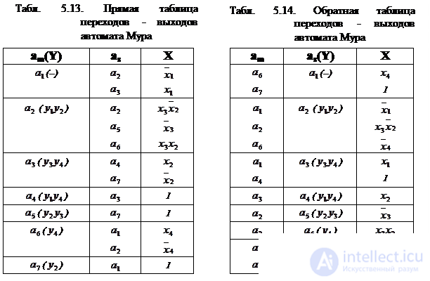
An example of a GSA, noted for the Moore's automaton, is presented in Fig. 5.16.
The graph of Moore’s automaton corresponding to the noted GSA (Fig. 5.16) is shown in Fig. 5.17. Its construction is similar to the construction of a graph for the Mile automaton.
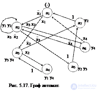
Table transitions-outputs Moore machine are presented in Table. 5.13 (direct) and table. 5.14 (reverse). Usually, for the Moore's automaton in the table of transitions-outputs, an additional column for the output signals is not used, and the output signal is recorded in the column, where the initial state a m or transition state a s is indicated.
Obtaining a graph or tables of transitions-outputs ends the stage of abstract synthesis of a microprogram automaton. As for finite automata, at the stage of abstract synthesis, it is possible to minimize the number of internal states of the automaton.
The structural synthesis of firmware automata after obtaining a graph or transition-output table is in principle similar to the canonical method of synthesizing digital automata. However, there are certain features primarily related to the fact that for real automata the number of memory elements and input signals can reach ten or more. The excitation functions and output signals are difficult to minimize, and in practice, minimization does not significantly simplify these functions with a large number of variables. Therefore, minimization is practically not used in the synthesis of firmware automata.
When performing structural synthesis, so-called structural tables of transitions and outputs are constructed, which can also be either direct or inverse.
Consider the stages of structural synthesis with specific examples.
Let us perform the structural synthesis of the Mile microprogram automaton given by its exit-transition table (Table 5.11 or Table 5.12). As an example, the synthesis will be performed in a straight table (table. 5.11).
1. In the original automaton, the number of states is M = 6, therefore, the number of memory elements is m =] log 2 M [=] log 2 6 [= 3. Let JK triggers be used for the synthesis.
2. We encode the internal states of the automaton using the Carnot map (Fig. 5.18) and, if possible, the neighboring coding method.
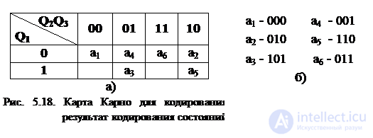
3. We build a direct structural table of transitions-exits of the Miles automaton (Table 5.15). In this table in the columns K (a m ) and K (a s ) indicates the code of the initial state and transition state, respectively. The column FV (excitation functions) indicates those values of the excitation functions that are necessarily equal to 1 at this transition. The rest (ie, equal to 0 or taking undefined values) are not indicated. This is equivalent to the fact that the value 0 is assigned to all indeterminate values of the excitation functions, which in general does not give a minimal function, however, in real automata, minimization is not usually done because of its inefficiency.
Tab. 5.15. Structural table of transitions-exits of the machine Miles
| a m | K (a m ) | a s | K (a s ) | X | Y | PV |
 |
 |
 |
 |
J 2 | ||
 |
 |
 |
J 3 | |||
|
|
 |
|
- | ||
 |
 |
 |
J 1 | |||
 |
 |
 |
J 3 | |||
 |
|
one | |
K 1 | ||
|
|
 |
 |
K 3 | ||
|
 |
 |
J 1 | |||
|
|
one | |
K 1 K 2 | ||
|
|
 |
- | K 2 K 3 | ||
|
 |
|
K 3 |
4. Для получения функций возбуждения поступаем следующим образом. Выражение для каждой функции получается в виде логической суммы произведений вида a i X , где a i – исходное состояние, X – условие перехода. Для упрощения полученных выражений выполняем все возможные операции склеивания и поглощения. В результате получаем следующие функции возбуждения:
 |
 |
 |
 |
 |
 |
5. Для получения функций выходов поступаем аналогично:
 |
 |
 |
 |
6. Для построения функциональной схемы автомата по полученным выражениям необходимо либо заменить a i его значениями через Q 1 Q 2 Q 3 либо получить сигнал, соответствующий a i . Обычно используют второй способ и для получения сигнала a i применяют так называемый дешифратор состояний , на вход которого поступают сигналы с выходов элементов памяти Q 1 Q 2 Q 3 . Кроме того, при построении схемы стараются выделить общие части , встречающиеся в функциях возбуждения или выходных сигналах. В этом случае окончательная система уравнений, по которым строится схема, будет иметь вид:
 |
 |
 |
 |
 |
 |
|
 |
|
|
|
 |
 |
|
 |
 |
 |
 |
|||
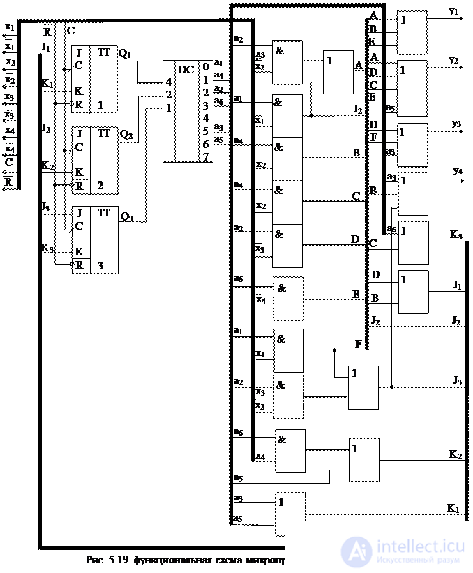
Функциональная схема автомата, построенная на основании полученных уравнений, представлена на рис. 5.19.
Выполним структурный синтез микропрограммного автомата Мура, заданного своей таблицей переходов-выходов (табл. 5.13 или табл. 5.14). В качестве примера синтез будем выполнять по обратной таблице (табл. 5.14).
В исходном автомате количество состояний М=7, следовательно число элементов памяти m = ] log 2 M [ = ] log 2 7 [ = 3. Пусть для синтеза используется D-триггеры.
2. Кодируем внутренние состояния автомата, используя алгоритм кодирования для D-триггеров ( чем больше переходов в это состояние, тем меньше единиц должно быть в коде этого состояния). Количество переходов в данное состояние легко определяется из обратной таблицы: a 1 ~ 2, a 2 ~ 3, a 3 ~ 2, a 4 ~ 1, a 5 ~ 1, a 6 ~ 1, a 7 ~ 2. Поэтому коды состояний следующие:
a 2 - 000, a 1 - 001, a 3 - 010, a 7 - 100, a 4 - 011, a 5 - 101, a 6 - 110.
3. Строим структурную таблицу переходов - выходов автомата Мура. Построение таблицы выполняется аналогично автомату Мили. Результат представлен в табл. 5.16.
Tab. 5.16. Структурная таблица переходов - выходов автомата Мура.
| a m | K(a m ) | a s (Y) | K(a s ) | X | ФВ |
| a 6 | a 1 (-) | |
D 3 | ||
| a 7 | one | D 3 | |||
| a 1 | a 2 (y 1 y 2 ) |  |
- | ||
| a 2 |  |
||||
| a 6 |  |
||||
| a 1 | a 3 (y 3 y 4 ) | |
D 2 | ||
| a 4 | D 2 | ||||
| a 3 | a 4 (y 1 y 4 ) |  |
D 2 D 3 | ||
| a 2 | a 5 (y 2 y 3 ) | |
D 1 D 3 | ||
| a 2 | a 6 (y 4 ) | |
D 1 D 2 | ||
| a 3 | a 7 (y 2 ) | |
D 1 | ||
| a 5 | D 1 |
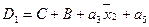
4. Выражения для функций возбуждения получаются в виде суммы произведений a i х , где a i – исходное состояние, х – условие перехода:
 ,
,  and
and 
или, если принять, что  ,
,  and
and  ,
,
 ,
,  and
and 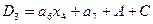
5. Выражения для выходных сигналов автомата Мура получаем, исходя из того, что эти сигналы определяются только внутренним состоянием автомата :
 ,
,  ,
,  and
and  .
.
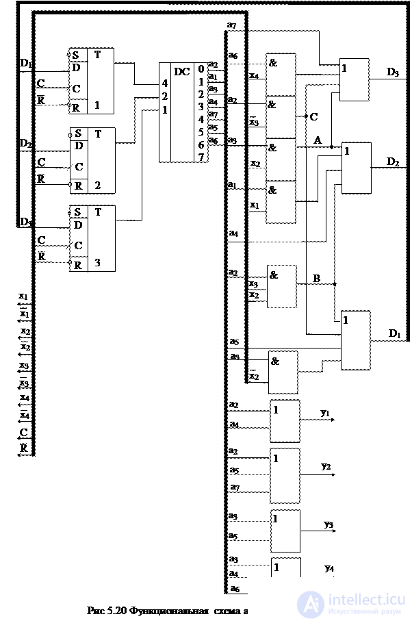
6. Для построения функциональной схемы автомата, как и в предыдущем случае, используем дешифратор состояний. Схема представлена на рис. 5.20.
Кроме рассмотренного ранее канонического метода, существуют и другие методы синтеза управляющих автоматов, среди которых наиболее широко используется синтез на базе регистра сдвига. Этот метод позволяет при построении схемы отказаться от дешифратора, т.к. состояния кодируются унитарным кодом. В автомате количество элементов памяти выбирается равным количеству внутренних состояний. В каждый момент времени только один триггер находится в 1, остальные в 0. Обычно при синтезе на базе регистра сдвига используются D -триггеры. Очень эффективен данный метод для так называемых линейных микропрограмм, т.е. микропрограмм без ветвлений (отсутствует логические условия). Рассмотрим пример синтеза управляющего автомата Мура данным методом. Пусть закодированная ГСА микропрограммы имеет вид рис. 5.21.
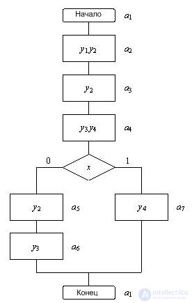
Рис.5.21 Закодированная ГСА
Разметив данную ГСА для автомата Мура, получаем семь состояний. Следовательно число триггеров m =7. Выполним синтез с использованием D -триггеров. Закодируем состояния унитарным кодом: a 1 =1000000, a 2 =0100000,..., a 7 =0000001. Обратная структурная таблица переходов-выходов для данного автомата представлена в таблице 5.17.
Таблица 5.17
| a m | Ka m | a s ( y) | Ka s | x | ФВ |
| а 6 | а 1 (-) | D 1 | |||
| а 7 | D 1 | ||||
| а 1 | а 2 ( y 1 y 2 ) | D 2 | |||
| а 2 | а 3 ( y 2 ) | D 3 | |||
| а 3 | а 4 ( y 3 y 4 ) | D 4 | |||
| а 4 | а 5 ( y 2 ) |  |
D 5 | ||
| а 5 | а 6 ( y 3 ) | D 6 | |||
| а 4 | а 7 ( y 4 ) | x | D 7 |
На основании структурной таблицы записываем выражения для выходных сигналов y i и функций D i :
D 1 = a 6 + a 7 y 1 = a 2
D 2 = a 1 y 2 = a 2 + a 3 + a 5
D 3 = a 2 y 3 = a 4 + a 6
D 4 = a 3 y 4 = a 4 + a 7
D 5 = 
D 6 = a 5
D 7 = a 4 × x
Because состояния автомата закодированы унитарным кодом, то можно отождествить каждое состояние с выходом соответствующего триггера, т.е. принять а i = Q i . Для принятого способа кодирования переход из одного состояния в другое как бы сопровождается сдвигом кода, записанного в семиразрядном регистре. Этим и объясняется название метода. Функциональная схема автомата Мура, построенная по полученным уравнениям, приведена на рисунке 5.22. При определенных навыках синтез автомата Мура на базе регистра сдвига выполняется непосредственно по отмеченной ГСА без построения структурной таблицы переходов-выходов.

1. Дайте общее описание цифрового автомата.
2. Нарисуйте структурные схемы асинхронного и синхронного цифровых автоматов.
3. Чем определяется абстрактный автомат.
4. Запишите законы функционирования автоматов Мили и Мура. Опишите их отличия.
5. Чем определяется абстрактный С-автомат.
6. Основные способы описания и задания автоматов.
7. Приведите примеры графов автомата Мили и автомата Мура. Опишите их отличия.
8. Дайте определение эквивалентности автоматов.
9. Преобразование графа автомата Мура в граф эквивалентного автомата Мили.
10. Преобразование графа автомата Мили в граф эквивалентного автомата Мура.
11. Опишите принцип микропрограммного управления и нарисуйте структурную схему операционного устройства с микропрограммным управлением.
12. Дайте определение операционного элемента.
13. Опишите вершины, используемые в граф-схемах алгоритмов.
14. Перечислите условия корректности граф-схемы алгоритма.
15. Нарисуйте примеры содержательной и кодированной граф-схемы алгоритма.
16. Нарисуйте пример кодированной ГСА и соответствующие графы переходов автомата Мура и Мили.
17. Порядок разметки ГСА автомата Мили.
18. Порядок разметки ГСА автомата Мура.
19. Построение прямой и обратной таблицы переходов-выходов автомата Мили по размеченной ГСА.
20. Построение прямой и обратной таблицы переходов-выходов автомата Мура по размеченной ГСА.
21. Построение прямой и обратной структурной таблицы переходов-выходов автомата Мили по размеченной ГСА.
22. Построение прямой и обратной структурной таблицы переходов-выходов автомата Мура по размеченной ГСА.
23. Получение функций возбуждения и функций выходов по структурной таблице переходов-выходов автомата Мили.
24. Getting the excitation functions and functions of the outputs on the structural table of transitions-outputs of the machine Moore.
25. Construction of a functional circuit of an automaton using expressions for its transition functions and output functions.
26. Features of building Miles and Mura automata based on shift registers.
Часть 1 Topic 5. Digital nodes circuit design
Часть 2 5.8. Abstract synthesis of Mile and Moore firmware control automata

Comments
To leave a comment
Computer circuitry and computer architecture
Terms: Computer circuitry and computer architecture