Lecture
"Automata Theory" is one of the important components of the federal state standard in the field of "Computer science and computing".
The theory of automata has wide application possibilities:
This can be judged by the speeches at the seminar "Software 2000 ..." scientists and specialists.
Doug Ross: "... 80 or even 90% of computer science (Computer Science) will in the future be based on the theory of finite automata ..."
Herver Gallaire: "I know people from Boeing who deal with aircraft stabilization systems using pure machine theory. It's hard to even imagine what they did with this theory."
Brian Randell: “Most of the theory of automata has been successfully used in system programs and text filters on UNIX. This allows many people to work at a high level and develop very effective programs.”
The simplest information transformer (Fig.1.1, a) maps a certain set of information elements X, which is input, to a certain set at output Y. If the sets X and Y are finite and discrete, that is, the conversion is carried out at discrete points in time, then such converters information are called finite transducers. The elements of the sets X and Y in this case are precoded with binary codes and construct the transformation of one set into another.
Conversion result  often depends not only on what information has appeared at the moment at the entrance, but also on what happened before, that is, on the background of the transformation. For example, one and the same entrance - a neighbor's apology after he stepped on his foot in a crowded bus - will cause you one reaction for the first time and a completely different one - for the fifth time.

Thus, there are more complex information converters (PI), the reaction of which depends not only on the input signals at the moment, but also on what was before, on the input history. Such PIs are called automata (memory circuits). In this case, they say about the automatic transformation of information (Fig. 1.1, b). It automatically reacts to the same input signal differently, depending on the state it was in. The machine changes its state with each input signal.
Consider a few examples.
Example 1 1 . An automaton describing the behavior of an intelligent father.
We describe the behavior of the father, whose son is in school and brings twos and fives. The father does not want to grab the belt every time the son gets a deuce, and chooses a more subtle upbringing tactic. Let us set such an automaton by a graph in which the vertices correspond to the states, and the arc from state s to state q, labeled x / y, is performed when the automaton from state s under the influence of the input signal x changes to state q with output reaction y. The graph of the automaton simulating the intelligent behavior of the parent is presented in Figure 1.2. This automaton has four states.  , two input signals - ratings
  and output signals
  which will be interpreted as the actions of the parent as follows:
 - take a belt;
 - scold your son;
 - to calm the son;
 - hope;
 - rejoice;
 - exult.
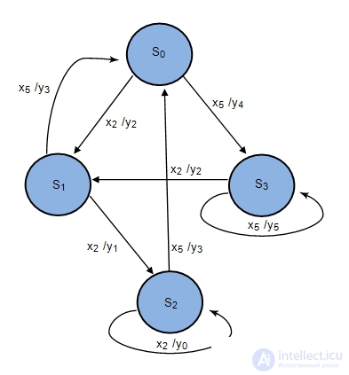
A son who has received the same grade, a two, is awaited at home by a completely different reaction of the father depending on the background of his studies. For example, after the third deuce in history  son will meet with a belt, but in history
  will soothe, etc.
The state machine can be implemented both in software and hardware. Software implementation can be performed on any high-level language in various ways. Fig. 1.3 shows the block diagram of the program that implements the behavior of the autosample 1. It is easy to see that the topology of the program block diagram repeats the topology of the automaton transition graph. Each state is associated with the NEXT operation, which performs the function of waiting for the next event of the arrival of a new input signal and reading it into some standard buffer x, as well as subsequent analysis of what signal it is. Depending on which signal came to the input, one or another function is performed.  and there is a transition to a new state.
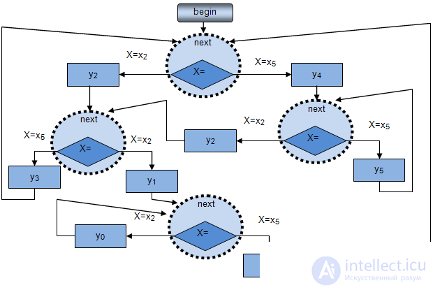
We consider the hardware implementation of the automaton in the second part of this section.
Example 2. "Student"
The automaton, the model of which is presented in Figure 1.4, describes the behavior of the student and teachers.
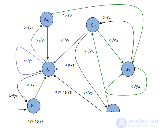
 - state;
 - input signals: "n", "2" and "5".
 - output reactions:
 - mark "n";
 - soothe;
 - we praise the student;
 - we encourage;
 - we hope;
 - we warn;
 - deduct;
Example 3 1 . Electronic clock (Fig. 1.5).
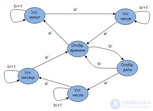
Electronic watches of various functionalities are one of the most widely used electronic devices in everyday life, the control of which is based on a finite-automatic model. They usually show: time, date; they have functions such as “set time and date”, “Stopwatch”, “Alarm”, etc. A simplified block diagram of the electronic clock is shown in Figure 1.5.
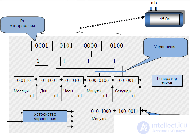
Registers display either time, or date, or a stopwatch depending on the "Office". The control device is based on a state machine model. The state machine responds to pressing the "a" button on the case by switching to the "Set minutes" state, in which the event of pressing the "b" button will cause an increase in the number. The control device is built on the basis of a state machine model whose graph is shown in Figure 1.6.
So. On the one hand, AUTOMATIC is a device that performs some actions without human intervention. On the other hand, AUTOMATIC is a mathematical model that describes the behavior of a technical device. In this case, the real device, system, etc. considered as some "BLACK BOX" (Fig. 1.7).

An abstract automaton is a mathematical model that describes a technical device with a set of input, output signals and states, in addition:
 called machine states;
 there is a finite set of output signals
  ;
; ;
; ;
; .
.That is, to describe the machine you need to use the six of the form  where
where


 .
.The automaton implements a mapping of the set of words of the input alphabet Z into the set of words of the output alphabet W.
An automaton is called finite if the set of its internal states and the set of values of the input signals are finite sets.
An automaton is called synchronous if the time-sampling interval is constant, otherwise it is an asynchronous automaton.
An automaton is called deterministic if the behavior of the automaton at each time instant is uniquely determined (  ,)
,)
Depending on the method of determining the output signal in synchronous automata there are distinguished:

 ;
; ,
,

To define a finite automaton S, it is required to describe all elements of the set

The most commonly used form for describing the elements of the set S is tabular, graphical, matrix methods.
To set the state machine  all elements of the set must be specified explicitly. So for the auto Miles:
 - the alphabet of states;
 - output alphabet;
 - input alphabet;


 - The initial state of the machine.
For example, Miles  presented in Table 1.3 are explicitly described as:

Moore's gun  presented in Table 1.8 are explicitly described as:

The tabular form for the Miles automaton is illustrated in Table 1.1.1 (transitions) and Table 1.2.2 (exits).
| z f \ a m | a 1 | ... | a M |
|---|---|---|---|
| z 1 |  |
 |
|
| ... | ... | ... | ... |
| z F |  |
 |
| z f \ a m | a 1 | ... | a M |
|---|---|---|---|
| z 1 |  |
 |
|
| ... | ... | ... | ... |
| z F |  |
 |
The rows of these tables correspond to the input signals, and the columns correspond to the states, with the leftmost column indicated by the initial state  . At the intersection of the column
  and strings
  ... in the transition table put the transition function
  , that is, the state in which the automaton passes from the state
  under the action of the input signal
  and in the output table - the output function
  i.e. output corresponding to this transition
  .
.
An example of the table method for setting the Mile machine is shown in Table. 1.3 (transitions) and table. 1.4 (outputs).
| z f \ a m | a 1 | a 2 | a 3 |
|---|---|---|---|
| z 1 | a 2 | a 1 | a 3 |
| z 2 | a 3 | a 3 | a 2 |
| z f \ a m | a 1 | a 2 | a 3 |
|---|---|---|---|
| z 1 | w 1 | w 2 | w 1 |
| z 2 | w 2 | w 2 | w 2 |
An automaton is called partially specified if it is not defined for all pairs of transitions (  ). For a partially specified automat in the place of the missing transition, a dash is placed in both the transition table and the output table.
An example of a tabular method for setting a partial automaton is shown in Table 1.5 (transitions) and Table 1.6 (outputs).
| z f \ a m | a 1 | a 2 | a 3 | a 4 |
|---|---|---|---|---|
| z 1 | a 2 | a 1 | a 3 | - |
| z 2 | a 3 | a 3 | a - | a 1 |
| z 3 | - | a 4 | a 2 | a 4 |
| z f \ a m | a 1 | a 2 | a 3 | a 4 |
|---|---|---|---|---|
| z 1 | w 1 | w 2 | w 1 | - |
| z 2 | w 2 | w 1 | - | w 2 |
| z 3 | - | w 1 | w 2 | w 1 |
The tabular form of the assignment of Moore’s automaton is a combined Table 1.7, in which the output signal corresponding to  Moore’s automaton is placed in the top line above the corresponding states, and the rest of the information is similar to the representation of the Mili automaton.
An example of the representation of Moore’s automaton is given in Table 1.8.
| \ w G | w 1 | w G | |
|---|---|---|---|
| z f \ a m | a 1 | ... | a m |
| z 1 |  |
 |
|
| ... | ... | ... | ... |
| z F |  |
 |
| \ w G | w 1 | w 3 | w 2 | w 1 | w 3 |
|---|---|---|---|---|---|
| z f \ a m | a 1 | a 2 | a 3 | a 4 | a 5 |
| z 1 | a 2 | a 1 | a 1 | a 1 | a 1 |
| z 2 | a 3 | a 5 | a 2 | a 5 | a 3 |
| z 3 | a 4 | a 3 | a 5 | a 2 | a 4 |
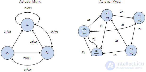
In this case, the machine  is represented by a graph in which:
 depicted by the vertices of the graph;
 given by arcs of the graph, with two vertices of the graph
  and
and  are connected by an arc if there is a transition from
  at
at  ;
; shown with arc marks:
  put on an arc from the top
  to the top
  if there is a transition from the machine
  at
at  under the action of the input signal
  ;
; specified by labels of arcs or vertices: for the Mile machine, an arc from a vertex
  to the top
  flagged output
  if there is a transition from the machine
  at
at  and this produces an output signal
  ;and for Moore’s automaton, the output
  is marked with a vertex that defines
 .
.Figure 1.8 shows examples of the description of the Mile automaton and the Moore automaton:
For the Miles automaton, the matrix form consists of a matrix of  dimension
  , where each element of the matrix
  located at the intersection of the
  ith row and the
  ith column corresponds to an input signal
  that causes a transition from state
  to state
  with generation of the output signal
 . An example of the matrix description of the Mile automat is shown below.

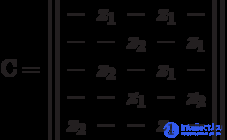
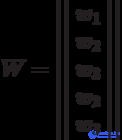
Для автомата Мура матричная форма состоит из матрицы  размерностью
  , где каждый элементматрицы
  , стоящий на пересечении
  -ой строки и
  -го столбца, соответствует входному сигналу
  , вызывающему переход из состояния
  в состояние
  Так как выходной сигнал
  . в автомате Мура зависит только от состояния, следовательно, выходные сигналы могут быть представлены матрицей-столбцом. Пример матричного описания автомата Мура показан на формуле, приведенной выше.
Comments
To leave a comment
Theory of Automata
Terms: Theory of Automata