Lecture
Annotation: Describes how to move from graph-circuit firmware to abstract machines. The GSA markup methods and the rules for constructing Mile and Moore automata on them are given. The concept of a combined automaton and methods of its presentation are given.
Keywords: definition, graph, graph vertices, microprogram, path, arc, logic function, unconditional transition, software, Mili automaton, Moore automaton, automaton, control device, abstract automaton, interval, input, combined automaton, multiple states
The transition is carried out in two stages. At the first stage, the number of states is determined by marking and marking the graph scheme; on the second, the definition of the automaton graph.
Markup rules:
 mark the vertex entry following the initial operator in the GSA and the entry of the final vertex. (Fig.4.1, a).
 - the inputs of the vertices following the operator vertices (Fig.4.1, b).
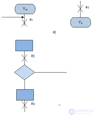
Fig. 4.1.
If as a result of the markup it turns out that several marked arrows enter the same vertex of the graph scheme, they are assigned the same symbol. Further symbol  considered as the initial state of the machine, and the characters
  - as intermediate states of the automaton. Thus, the number of states of the automaton is determined by the number of different symbols
The transition from the marked graph-schemes to the graph of the automaton is carried out in the following order.
The graph vertices represent all the states of the automaton and the symbols are written inside the circles.  , i.e. existing tags on the GSA.
On the graph-diagram of the firmware, the path is searched between two adjacent states.  and
and  . Paths are displayed by arcs. There may be three types of paths:
 and
and  graph of an automaton, is marked by a logical function
  whose value determines the transition of the automaton from the state
  in state
  and the operator
  located between
  and
and  (Fig.4.2).

 and
and  graph of an automaton, is marked by a logical function, the value of which determines the transition of the automaton from the state
  in the as state and if on the way between
  and
and  there is no operator vertex, then this fact is marked with a '-' symbol or a symbol
  (empty operator, skip tact) (Fig.4.3);

 located between
  and
and  (Fig.4.4).
Fig. 4.4.
The construction of the graph of the Mili automaton using the GSA firmware will be considered on the example of the GSA presented in Fig.4.5.
At the first stage, we will execute markup according to the above rules. We get five labels, highlighted by red crosses in Fig.4.5.
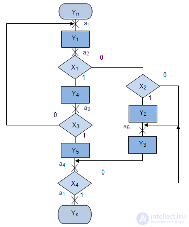
Fig. 4.5.
At the second stage we build the graph of Moore’s automaton. We have five vertices of the graph corresponding to five states.
By GAW we find all the paths between adjacent marks. So from the label  in tag
  there is a path of the third type, that is, an unconditional transition. This path passes through the operator vertex marked by the signal
  which is carried out on the transition arc from the state
  in state
  .
.
Consider the paths leading from the label.  . There are three of them. First way out
  at
at  passes through conditional vertex
  and operator vertex
  that is, it is the path of the first kind, corresponding to the transition from the state
  in state
  by condition
  with output signal
  . Second way out
  at
at  passes through conditional vertices
  and
and  and operator vertex
  that is, it is the path of the first kind, corresponding to the transition from the state
  in state
  by condition
  with output signal
  .
.
Third way out  at
at  passes through conditional vertices
  and
and  and does not pass through any operator vertex, that is, it is a path of the second kind, corresponding to the transition from the state
  in state
  by condition
  no output signal.
Consider the paths leading from the label.  . There are two of them. First way out
  at
at  passes through conditional vertex
  and operator vertex
  , that is, this is the path of the first type, corresponding to the transition of the automaton from the state
  in state
  by condition
  with output signal
  . Second way out
  at
at  goes through the same conditional vertex
  and does not pass through any operator vertex, that is, it is a path of the second kind, corresponding to the transition from the state
  in state
  by condition
  no output signal.
From tags  there are also two ways and both of the second type without output: from
  at
at  corresponding to the transition from the state
  in state
  by condition
  ; of
; of  at
at  corresponding to the transition from the state
  in state
  by condition
  .
.
Of  there is one way in
  the third type, passing through the operator peak
  .
.
The result of the constructed abstract Mile automaton is shown in Fig.4.6.
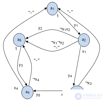
Fig. 4.6.
If we redesign the signals on arcs, for example, replacing  on
on  ,
,  on
on  etc., and
  on
on  ,
,  on
on  , etc., we get the abstract Mile machine gun in its usual form.
The transition is also carried out in two stages. At the first stage, the number of states is determined by marking and marking the graph scheme; on the second, the definition of the automaton graph.
Markup rules:
 mark the starting and ending vertices of the GSA firmware.
 mark the operator vertices (Fig.4.7, b).
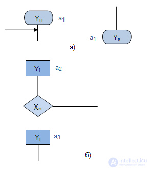
At the second stage, we construct the graph of Moore’s automaton, and the labels correspond to the vertices of the graph within which the output signal is recorded, since in the Moore’s automaton, the output signal depends only on the state and does not depend on the input signal.
As a result of the analysis of the markup, we see that between pairs of tags we have paths of the second and third types. Each path set the appropriate transition.
The construction of Moore’s automaton will be considered on the example of the GSA MP presented in Fig. 4.8.
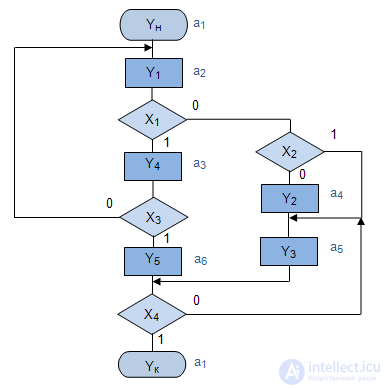
Fig. 4.8.
At the first stage, we will execute markup according to the above rules. We get six tags (Fig.4.8).
At the second stage, we build the graph of the Mile automaton. We have six vertices of the graph corresponding to six states. Inside each vertex we write the corresponding output signal.
By GAW we find all the paths between adjacent marks. So from the label  in tag
  there is one path of the third type, that is, an unconditional transition. This path is represented by a transition arc from the state
  in state
  .
.
Consider the paths leading from the label.  . There are three of them. First way out
  at
at  passes through conditional vertex
  that is, this is the second type of path, corresponding to the transition from the state
  in state
  by condition
  . The second path passes through conditional vertices.
  and
and  that is, this is also the path of the second kind, corresponding to the transition from the state
  in state
  by condition
  . Third way out
  at
at  passes through conditional vertices
  and
and  that is, this is the path of the second kind, corresponding to the transition from the state
  in state
  by condition
  . The result of the constructed abstract Mile automaton is shown in Fig. Fig.4.9 /
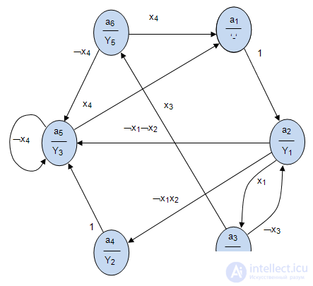
Fig. 4.9.
Very often, control devices require signals of both types: the first kind as in the abstract Mily machine and the second kind as in the abstract Moore machine. In Miles, the output signal depends on both the state and the input signal and is formed in the same discrete time interval in which the input signal arrives (Fig. 4.10, a).

Fig. 4.10.

In Moore’s automaton, the output signal depends only on the state, and the entire time when the automaton is in this state is output (Fig. 4.10 b):

The combined automaton or  automaton thus contains signals of both the first kind and second and is described by a figure of eight of the form:

Where  - The set of states of the machine;
 - many input signals;
 - a set of output signals of the first kind;
 - a set of output signals of the 2nd kind;


При графическом задании  - автомата на переходах указываются выходные сигналы 1 рода
  , а в вершинах выходные сигналы 2 рода
  (рис.4.11).
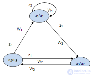
Fig. 4.11.
Явное задание  - автомата требует описание всех составляющих и выполняется так же как и для автоматов Мили и Мура.
Табличное задание  - автомата состоит в представлении работы автомата двумя таблицами: таблицей переходов (табл.4.1) и таблицей выходов (табл.4.2), в которой в отличие от автомата Мили в верхней строке добавляются сигналы второго рода.
| z\a | a 1 | a 2 | a 3 |
|---|---|---|---|
| z 1 | a 3 | a 1 | a 1 |
| z 2 | a 1 | a 3 | a 2 |
| \u h | u 1 | u 3 | u 2 |
|---|---|---|---|
| z\a | a 1 | a 2 | a 3 |
| z 1 | w 1 | w 1 | w 2 |
| z 2 | w 1 | w 2 | w 1 |
The matrix task of  an automaton consists in the description by two matrices similarly to the matrix representation of the Mily and Moore automata.

Comments
To leave a comment
Theory of Automata
Terms: Theory of Automata