Lecture
4. RELIABILITY OF NON-RECOVERABLE SYSTEM WITH THE MAIN CONNECTION OF ELEMENTS
4.1. Determination of the probability of failure-free operation and the average time to failure
Most systems are designed so that if any of the elements fail, the system fails. When analyzing the reliability of such a system, we assume that the failure of any of the elements is random and independent and does not cause changes in the characteristics (does not violate the performance) of the other elements. From the point of view of the theory of reliability in a system where the failure of any of the elements leads to a system failure, the elements are included according to the basic scheme or sequentially. In the concept of failure, there is a physical analogue of an electrical circuit with a series connection of elements, when the failure of any of the elements is associated with an open circuit. But very often, when calculating reliability, it is necessary to consider the physical parallel inclusion of elements as the sequential inclusion of calculation elements. For example, some consumer *** consumes electricity through two identical cables, and the cross section of the wires of one cable is not able to miss the entire electrical load of the consumer. If one cable fails, the remaining one is subjected to an unacceptable overload, and this cable is disconnected using protection — the power supply system fails, that is, the failure of one of the cables causes a power supply failure. Therefore, when calculating reliability, cables, as design elements, have a consistent basic switching circuit.
Suppose that the system consists of n series-connected elements. It is known from probability theory that if the probabilities of occurrence of several independent random events are determined, then the coincidence of these events is determined as the product of the probabilities of their occurrences [4, 11, 13]. In our case, the operational state of any of the n elements of the system is estimated as the probability of failure-free operation of the element. The system will be in a healthy state only if the working states of all elements match. Thus, the performance of the system is estimated as the product of the probabilities of failure-free operation of the elements:
 , (4.1)
Where  - the probability of failure of the i-th element.
The system, as well as the element, can be in one of two incompatible states: failure or operation. Consequently,
 ,
,  ,
,
where Q (t) is the probability of system failure, determined by the expression:
 . (4.2)
With an arbitrary law of distribution of time to failure for each of the elements:
 , (4.3)
Where  - the failure rate of the i-th element.
The probability of failure-free system, respectively, will be written:
 . (4.4)
By expression (4.4), it is possible to determine the probability of a system to work without failure before the first failure with any law of change in the failure rate of each of the n elements over time.
For the most commonly used condition  = const expression (4.4) takes the form:
 , (4.5)
Where  can be represented as the failure rate of a system reduced to an equivalent element with a failure rate:
 = const.
Thus, it is easy to replace a system of n consecutive elements with an equivalent element that has an exponential law of probability distribution of trouble-free operation. And this means, if l o = const, then the average operating time to
system failure  . It is also true that subject to:
l o = const, the desired value is determined as  .
.
In the case of l№ const, the mean time to failure of the system is determined by the expression:
 , (4.6)
where P (t) is found by expression (4.4).
4.2. An example of calculating the reliability of a system assembled according to the main scheme
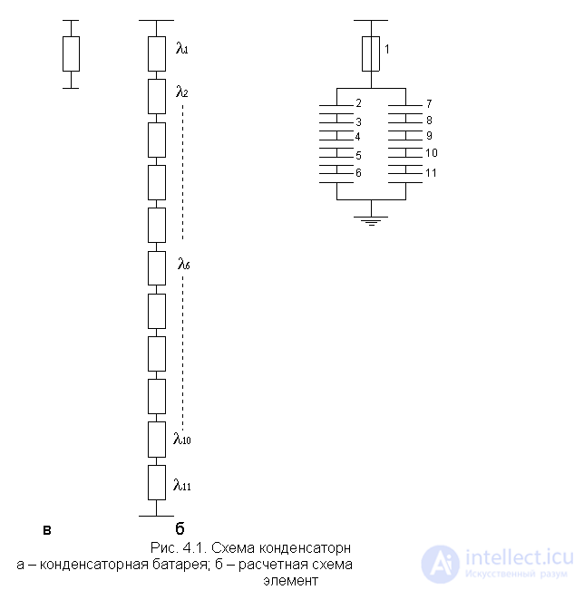
In fig. 4.1, and the connection diagram of the capacitor battery is presented ( l 2 = l 3 = ... l 11 = 0.01 1 / year,  = 0.024 1 / year). The capacitors are chosen so that when any of them fail, the battery does not fulfill its functions, that is, from the point of view of reliability, it fails.
It also fails when a fuse blows out 1. Therefore, we formulated the notion of failure - if any of the elements fail, the system consisting of 11 elements fails. In fig. 4.1, b shows the calculated reliability scheme, where all elements are connected in series.
The failure rate of a capacitor battery will be:
 .
.
In fig. 4.1, the battery is represented by an equivalent cell with a failure rate of l o . With respect to a more complex system (circuit), in which the capacitor battery is an integral part, this setting will be an element with the l o parameter .

The probability of battery failure for the year is:

Mean time to failure is:
 of the year.
The result of the calculation proves that the reliability of the non-repairable capacitor bank, for 1 year of continuous operation, is low. To ensure a higher level of reliability, it is necessary to provide better maintenance. The effect of maintenance is discussed in detail in [1, 9].
Comments
To leave a comment
Theory of Reliability
Terms: Theory of Reliability