Content
Introduction
Polyphase FFT circuit
Possible loss of harmonics with polyphase FFT. Choosing the right smoothing window
Examples of using polyphase FFT
findings
Introduction
A large number of publications on foreign sites on the topic of polyphase FFT, accompanied by very scarce information in the literature. Meanwhile, interest in this topic is fueled by supposedly “super resolution” in frequency when using polyphase FFT compared to the “classical” transformation. In this article we will try to deal with this “super resolution” and get a complete picture of the algorithm.
Polyphase FFT circuit
Polyphase FFT is performed as shown in Figure 1.
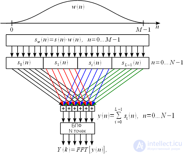
Figure 1: Polyphase FFT Diagram
Source signal


multiplied by the weight window

resulting in a signal


. This signal is divided into

equal parts

counts, "shortened" signals are formed


These "shortened" signals are added up by the term and one total signal is formed.
 |
(one) |
Next is taken

- point FFT from

and the spectrum is obtained


Let us consider the spectrum from the entire weighted signal.

long

counts:
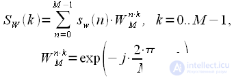 |
(2) |
Imagine in the expression (2)

as a sum of non-intersecting “shortened” samples

, then:
 |
(3) |
Consider that

then
 |
(four) |
Expression (3) is

- dotted DFT, and we need

- point. Consider only

- th spectrum readings


, then (3) with regard to (4):
 |
(five) |
You may notice that:
 |
(6) |
Then
 |
(7) |
We take into account (1) then (7) we rewrite to the form:
 |
(eight) |
Thus, we can conclude: the spectrum at the output of the polyphase FFT is thinned out in frequency

times the spectrum of the original weighted signal. This statement is experimentally verified and true. An example of such thinning is shown in Figure 2.
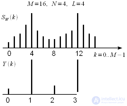
Figure 2: Thinning in frequency L = 4, M = 16
At the same time we get the spectrum of length

, with good frequency resolution because window smoothing was applied, and from it we only select

counts by thinning in frequency, it only requires

- point FFT.
Possible loss of harmonics with polyphase FFT. Choosing the right smoothing window
Since frequency thinning is used in polyphase FFT, it is possible that when thinning the useful signal harmonics are lost. For example, if the signal will look like that shown in Figure 3, then, obviously, we are choosing each

- the second countdown “jump over” the harmonic and do not notice it in the spectrum.
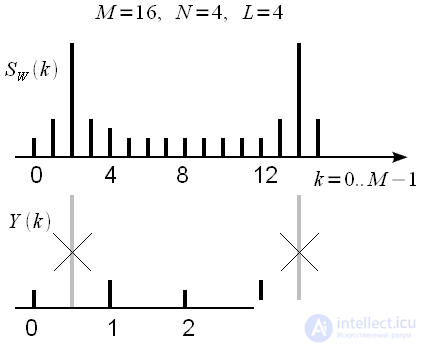
Figure 3: Loss of harmonics during frequency thinning
High resolution in frequency with us playing a cruel joke. In order for the spectral harmonics not to be “lost” as a result of time thinning, the weight window

must be such as to ensure the expansion of the spectral peak to

counts. In this case, we will not be able to jump over it choosing each

- th spectral countdown. This is clearly shown in Figure 4. Figure 4a shows the spectrum

,

source signal

,

without window processing, figure 4b - the result of weight smoothing

,

, sharp peaks became wide with one peak being “smeared” on

counts, and finally in Figure 4c - polyphase FFT without losing harmonics.
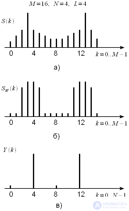
Figure 4: Choosing the right smoothing window doesn’t let you lose the harmonics
Examples of using polyphase FFT
We illustrate all of the above experimentally. Take the original signal

. Sample rate we take

Hz, the number of reference samples

,

Hz

Hz Choose

.
The results of the experiment are shown in Figure 5. The blue spectra are the result of polyphase FFT, the red 1024 point FFT with a smoothing Hamming window.
Figure 5: Application of Polyphase FFT
Figure 5a. Frequencies

Hz

Hz Hamming window with 1024-point FFT (without polyphase processing), and with polyphase FFT at 4096 points. We fall exactly on the harmonics and see an increase in the resolution in the spectrum. This example shows how much better the resolution in the spectrum is when using polyphase FFT. At the same time, the computational costs are approximately the same both for 1024 point FFT without polyphase processing, and for polyphase FFT by 4096 points (

).
Figure 5b. Frequencies

Hz

Hz Hamming window with 1024-point FFT (without polyphase processing), and with polyphase FFT at 4096 points. An example of how the use of polyphase FFT leads to a loss of harmonics due to an improperly chosen width of the smoothing window (the Hamming window is too narrow).
Figure 5c. Frequencies

Hz

Hz Hamming window with 1024-point FFT (without polyphase processing), and Blackman window with polyphase FFT at 4096 points. It can be seen that the Blackman window is much better suited for polyphase FFT, since the lost harmonic is much higher than with the Hamming window, but still the Blackman window is not wide enough, since the harmonic level is 20 dB lower than it should be.
Figure 5d. Frequencies

Hz

Hz Hamming window with 1024-point FFT (without polyphase processing), and Blackman-Harris window with polyphase FFT at 4096 points. It can be seen that the expansion of the smoothing spectral window (Blackman-Harris "low-resolution window) increases the amplitude of the" lost "harmonics, but still not enough.
Figure 5e. Frequencies

Hz

Hz Hamming window with 1024-point FFT (without polyphase processing), and maximum flat window with polyphase FFT at 4096 points. The level of the lost harmonics is slightly lower than the real level (approximately by 2 ... 3 dB). But there is an expansion of the main peak in polyphase processing.
Figure 5e. Frequencies

Hz

Hz Hamming window with 1024-point FFT (without polyphase processing), and maximum flat window with polyphase FFT at 4096 points. The possibility of distinguishing adjacent signals is shown, whereas with a normal FFT, they merge.
findings
So we can conclude. Polyphase FFT significantly reduces computational costs by replacing

- dotted FFT

- point, or at the same computational cost allows for a good resolution of the spectral analysis. Increasing the resolution of the analysis is provided by polyphase signal processing over a long time interval. Since the length of the original signal during polyphase processing in

times longer, then the resolution is higher.
The algorithm has disadvantages:
1. Sensitivity to the choice of a smoothing window. Wrong window selection leads to loss of signal harmonics. This must be taken into account when using polyphase FFT.
2. Polyphase FFT is a lossy transform and there is no inverse transform for it.
3. For polyphase FFT requires a long initial sample.
The scope of polyphase FFT - spectral analyzers, when there are no stringent requirements for measuring the signal level. Where harmonic loss is unacceptable, polyphasic FFT should be used with caution.


 multiplied by the weight window
  resulting in a signal
 . This signal is divided into
  equal parts
  counts, "shortened" signals are formed

 These "shortened" signals are added up by the term and one total signal is formed.
 - point FFT from
  and the spectrum is obtained

 long
long  counts:
 as a sum of non-intersecting “shortened” samples
  , then:
 then
then
 - dotted DFT, and we need
  - point. Consider only
  - th spectrum readings
 , then (3) with regard to (4):


 times the spectrum of the original weighted signal. This statement is experimentally verified and true. An example of such thinning is shown in Figure 2.
 , with good frequency resolution because window smoothing was applied, and from it we only select
  counts by thinning in frequency, it only requires
  - point FFT.
 - the second countdown “jump over” the harmonic and do not notice it in the spectrum.
 must be such as to ensure the expansion of the spectral peak to
  counts. In this case, we will not be able to jump over it choosing each
  - th spectral countdown. This is clearly shown in Figure 4. Figure 4a shows the spectrum
  ,
,  source signal
  ,
,  without window processing, figure 4b - the result of weight smoothing
  ,
,  , sharp peaks became wide with one peak being “smeared” on
  counts, and finally in Figure 4c - polyphase FFT without losing harmonics.
 . Sample rate we take
  Hz, the number of reference samples
  ,
,  Hz
Hz  Hz Choose
  .
. Hz
Hz  Hz Hamming window with 1024-point FFT (without polyphase processing), and with polyphase FFT at 4096 points. We fall exactly on the harmonics and see an increase in the resolution in the spectrum. This example shows how much better the resolution in the spectrum is when using polyphase FFT. At the same time, the computational costs are approximately the same both for 1024 point FFT without polyphase processing, and for polyphase FFT by 4096 points (
  ).
). Hz
Hz  Hz Hamming window with 1024-point FFT (without polyphase processing), and with polyphase FFT at 4096 points. An example of how the use of polyphase FFT leads to a loss of harmonics due to an improperly chosen width of the smoothing window (the Hamming window is too narrow).
 Hz
Hz  Hz Hamming window with 1024-point FFT (without polyphase processing), and Blackman window with polyphase FFT at 4096 points. It can be seen that the Blackman window is much better suited for polyphase FFT, since the lost harmonic is much higher than with the Hamming window, but still the Blackman window is not wide enough, since the harmonic level is 20 dB lower than it should be.
 Hz
Hz  Hz Hamming window with 1024-point FFT (without polyphase processing), and Blackman-Harris window with polyphase FFT at 4096 points. It can be seen that the expansion of the smoothing spectral window (Blackman-Harris "low-resolution window) increases the amplitude of the" lost "harmonics, but still not enough.
 Hz
Hz  Hz Hamming window with 1024-point FFT (without polyphase processing), and maximum flat window with polyphase FFT at 4096 points. The level of the lost harmonics is slightly lower than the real level (approximately by 2 ... 3 dB). But there is an expansion of the main peak in polyphase processing.
 Hz
Hz  Hz Hamming window with 1024-point FFT (without polyphase processing), and maximum flat window with polyphase FFT at 4096 points. The possibility of distinguishing adjacent signals is shown, whereas with a normal FFT, they merge.
 - dotted FFT
  - point, or at the same computational cost allows for a good resolution of the spectral analysis. Increasing the resolution of the analysis is provided by polyphase signal processing over a long time interval. Since the length of the original signal during polyphase processing in
  times longer, then the resolution is higher.
Comments
To leave a comment
Digital signal processing
Terms: Digital signal processing