
Lecture
Monoblock design method - the equipment circuit is not broken down into separate functional units, but is realized as a single integral structure on one mounting base.
Module design method - a feature of building technical systems that consists in subordinating their dimensions to a design module and (or) in providing the ability to assemble a wide variety of complex non-standard technical systems with widely differing characteristics from a small, economically justified, number of types and standard sizes of identical primary (standard or unified) common module-elements.
Factors determining the choice of the monoblock method:
Monoblock design method
Advantages:
Disadvantages:
A modular structure is a structure (per ESKD - a product structure) built on the modular principle.
A structural module (SM) is a part of a product's structure. A structure is usually understood as the totality of all parts and assembly units that form the product.
A functional module (FM) is a part of the product itself, implemented as an SM and performing a specific function or group of functions.
Basic module design methods
The functional-module method consists in creating equipment based on a catalog of function-standardized modules (design based on a standardized parametric range of modules).
The functional-unit method is based on dividing the entire electrical circuit into functionally complete units and using unified structures of the 1st structural level of the selected (or specified in the technical specification) BNK system.
In the block-module method, the equipment layout is assembled from large modules produced by various companies in the form of conversion units, memory units, power-supply units, etc.
In the functional-block method, functionally complete devices based on original circuits not found in block-module catalogs are implemented either as complete block-module structures using the selected BNK system, or in an original design consisting of a number of functional modules combined into a single structure - a block.
2. Growth in equipment complexity and packing density.
3. Reduction in the relative dimensions of active elements and the energy level of signals.
4. Growth in the specific power dissipated by active elements.
LAYOUT OF ELECTRONIC EQUIPMENT UNITS
Layout is the process of arranging component modules, electronic components and parts of electronic equipment on a plane or in space, determining their basic geometric shapes and dimensions.
The following must be taken into account:
Purpose of bearing structures
A bearing structure (BS) is intended for placing, arranging and interconnecting electronic components and other constituent parts of a product in order to ensure its stable operation and protection from the effects of unfavorable operating conditions.
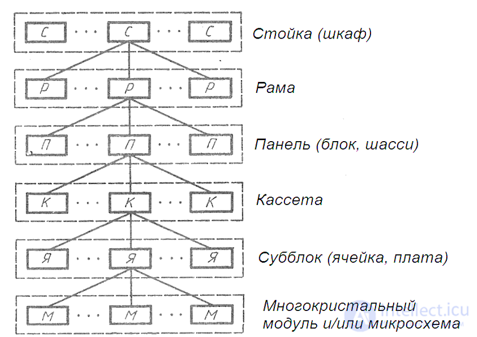
Diagram of structural hierarchy
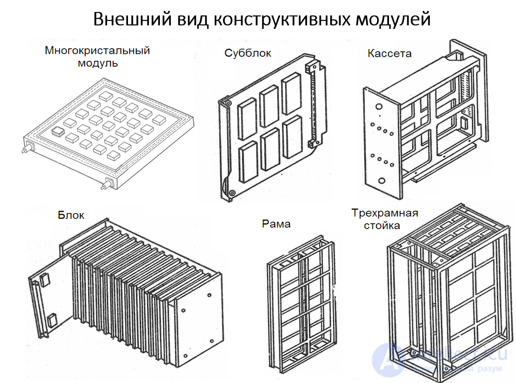
Appearance of structural modules
Structural hierarchy of electronic-equipment modules
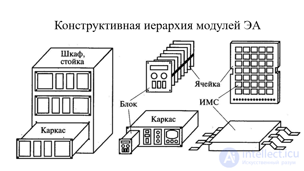
An electronic cabinet (rack, cabinet stand, console) is intended for housing radio-electronic systems and complexes. A functionally complete electronic cabinet is built on the basis of a third-level basic bearing structure (BNK-3) and possesses structural interchangeability.
An electronic frame (rack, cage) is intended for housing electronic devices. A functionally complete electronic unit is built on the basis of BNK-2 and possesses structural interchangeability
An electronic cell is intended for housing radio-electronic units. A functionally complete electronic cell (board) is built on the basis of BNK-1 and possesses structural interchangeability.
An IC (microassembly, microcircuit) is a functionally and structurally complete electronic device, dimensionally coordinated with BNK-1 and possessing structural interchangeability.
In addition to the requirements determined by their purpose, bearing structures must:
Sequence of decision-making on structural options for the modular layout of instruments and units:
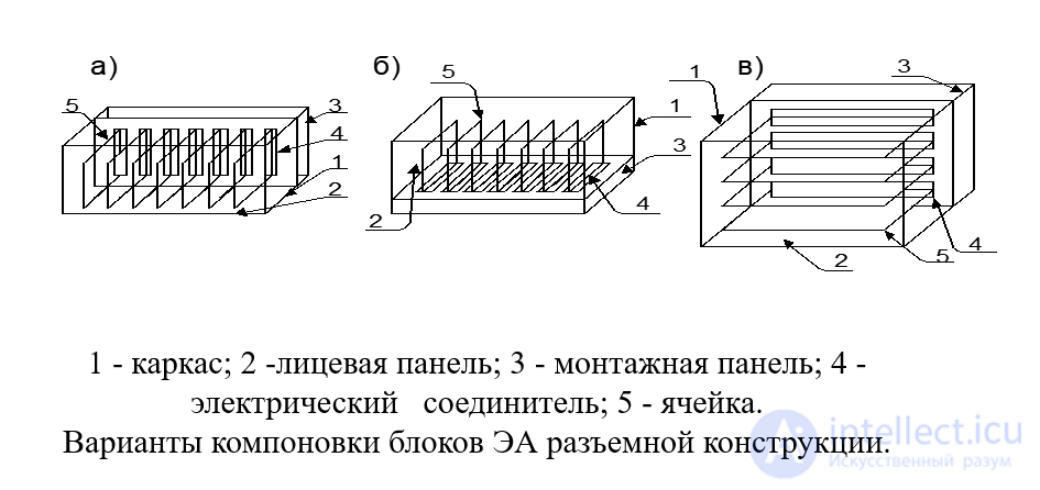
1 - frame; 2 - front panel; 3 - mounting panel; 4 - electrical connector; 5 - cell.
Layout options for plug-in-construction electronic-equipment units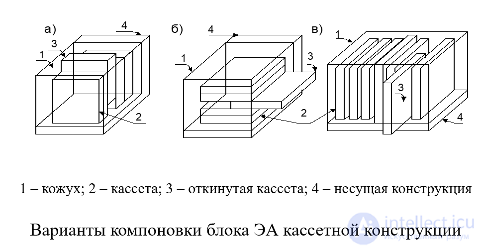
1 - housing; 2 - cassette; 3 - swung-out cassette; 4 - bearing structure
Layout options for cassette-construction electronic-equipment units

Comments