
Lecture
Transmission lines (TL). Electrical connections are understood to mean transmission lines (TL) and electrical contacts used to transfer signals and electrical energy between technical devices, radio components and modules that make up electronic equipment. Electrical connections may be intra-module and inter-module, intra-unit and inter-unit, and so on, which determines their design implementation.
By the functions they perform, a distinction is made between signal TLs, which link the inputs
and outputs of elements and modules and are intended for transmitting signals, and power-supply TLs, which deliver electrical energy to the elements.
Every TL has a forward and a return conductor. The return conductor is called ground,
the zero-potential line, or the common conductor. There are unshielded and
shielded TLs. Shields protect lines from the effects of electric, magnetic and electromagnetic fields. Depending on the design features of
the return conductor, TLs are divided into balanced ones, consisting of
two identical insulated conductors, unbalanced ones with a single common conductor
shared by many TLs, and coaxial ones, with the return conductor formed by the braid of a coaxial cable.
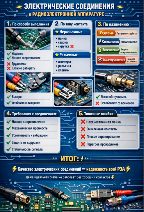
In general, transmission lines must have:
There is no universal TL that satisfies all these requirements at once. In actual designs, different types of TL are used depending
on the purpose and functional features of the equipment. The choice of TL type is influenced
by the shape of the transmitted signals, their voltage and frequency, signal
attenuation per unit length of line, mechanical flexibility, process requirements
and other factors.
Electronic devices contain elements and modules that are diverse in the functions they perform, differing in the nature of the signals processed, their power, frequency, etc. When electrical signals are transmitted over a TL,
the shape and spectrum of the signals become distorted, and they are attenuated. The degree of signal distortion is determined by how well the parameters of the electronic circuits are matched
to the parameters of the TL, by the mutual influence of neighboring TLs, and by signal delay in the TL. The choice of a design and process solution for implementing electrical connections is an important and complex task that affects the quality
of the electronic equipment being designed.
An electrical signal is carried by a current-carrying conductor, which may be a metal wire (wire), or film and printed conductors. In cross-section,
wires may be round or rectangular, while film and printed conductors are
rectangular. Wires are protected by insulating dielectric sheaths and, where necessary, by shields. Waveguides and fiber-optic
TLs carry electromagnetic energy in the radio-frequency (waveguide) and optical (light guide) ranges.
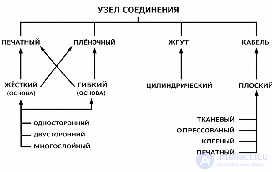
(Fig. 5.1.1), grouped, for example, into harnesses of several dozen lines.
To improve labor productivity when assembling electronic equipment and to simplify
wiring work, TLs are combined, in terms of design and process, into assemblies
Power-supply lines are bulk wires, film and printed conductors, or electrically conductive plates. The design implementation of signal
TLs is more varied and is largely determined by the frequency range of the signals.
All signal transmission lines are divided into electrically long and electrically
short ones, in which the nature of signal distortion differs.
A TL is called electrically short if its length for a harmonic
signal is determined by the expression
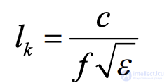
where f is the signal frequency, c is the speed of light, and e is the relative dielectric constant of the medium surrounding the transmission line.
The TL calculation for pulse signals is performed for the harmonic
of the highest frequency, whose value
is approximately equal to
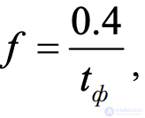 , where tf is the value of the signal edge at the 0.1
and 0.9 amplitude levels of the signal
Electrically short TLs.
When
analyzing the electrical processes, a short
TL is modeled by an equivalent circuit consisting of the capacitance and inductance of the TL, lumped at a single point (Fig. 9.1.2-b). The resistive
resistance of the line is neglected. Module 1
forms the signal, represented by a voltage source U with a series-connected resistance R1. Module 2 is the signal receiver and is modeled by an input
resistance R2.
When R2 >> R1, the equivalent circuit of the inductive-capacitive short line
together with resistance R1 can be represented as a resonant circuit, in which oscillations may arise at a frequency of:
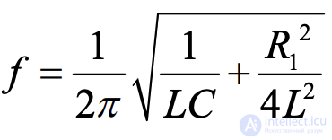
As a result of the oscillating process, the voltage at the input of circuit 2 may repeatedly cross its triggering threshold and cause repeated changes in its
logic state. If the oscillations in the TL die out within a time shorter than the duration of the signal edge being transmitted along the line, they will not affect the operability of the equipment. The condition for the absence of oscillations in the line is satisfied when
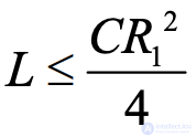 In this case the inductance of the line can be neglected (v).
The response of the capacitive TL (v) to a sinusoidal signal will manifest itself in
a reduction of the output voltage amplitude and a phase shift of the output signal relative to the input signal. In general, the signals at the input and output of the TL can
differ substantially. If the TL is loaded onto threshold circuits, then when a rectangular pulse of amplitude U is applied to the TL input, the switching time of the
circuit is delayed by an amount:
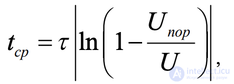
where R C1
t = – time constant, Unop is the threshold voltage of logic element 2.
If the pulse duration is much greater than τ, the TL will pass the pulse practically without distortion. Otherwise the transmission line will behave like an integrating RC circuit, lowering the pulse amplitude and rounding off its
edges.
Crosstalk is caused by electric, magnetic and electromagnetic interaction between neighboring TLs. Microminiaturization and
increasing conductor packing density confront the designer with
the important task of reducing interference to levels that do not affect the accurate and
reliable operation of the equipment. The interference level depends on the mutual inductance of the conductors and the inter-conductor capacitance, creating, respectively, inductive and capacitive components of mutual interference. The capacitive component grows with the rate of change of the voltage at the TL input and with the values of the resistances at the ends of the line,
while the inductive component grows with the rate of change of current in the line and with an increase in the number of loads at the output of the active line.
The stray capacitance between TLs can be reduced by shortening the length over which wires run parallel to one another to the minimum possible.
distance from each other, by increasing the gap between them, by routing wires carrying signals of different levels in separate harnesses, by bringing
the TL closer to ground, by introducing shielded wires, and by using coaxial cables. For example, grounding the braid of a coaxial cable allows
the capacitive interference to be eliminated entirely. Mutual inductance can be weakened
by spacing the TLs as far apart from each other as possible, by reducing the area of the loops formed by the wires
carrying the forward and return TL currents, and by using shielded wires, twisted pairs, and coaxial cables.
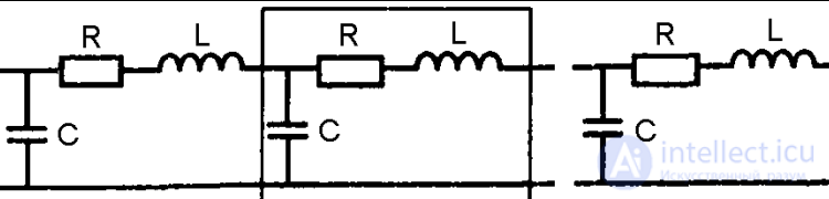
Although the line parameters are distributed
along its length, in the equivalent electrical circuit of the TL they are approximated as
lumped over short segments of the line (Fig. 5.1.3), where R, L, C are the per-unit-length
(per unit length)
resistance, inductance and capacitance. The most important characteristic of an electrically
long TL is its
characteristic impedance Z0.
Characteristic impedance is the impedance a line presents
to an electromagnetic wave in the absence of reflections from the ends of the line. It depends on the primary electrical parameters of the cable and on the signal frequency.
If the electromagnetic wave is represented as separate voltage and current waves, then the ratio between them is the characteristic impedance of the circuit:
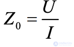
The characteristic impedance is a complex quantity and consists of a resistive and a reactive part. The frequency dependence of the characteristic impedance rises in
the low-frequency region and is capacitive in nature (2pfL< at higher frequencies 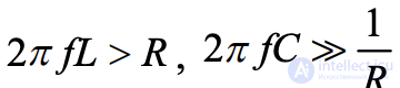 holds, and the value of the characteristic impedance tends toward
a constant value, which is taken as the value of Z0.
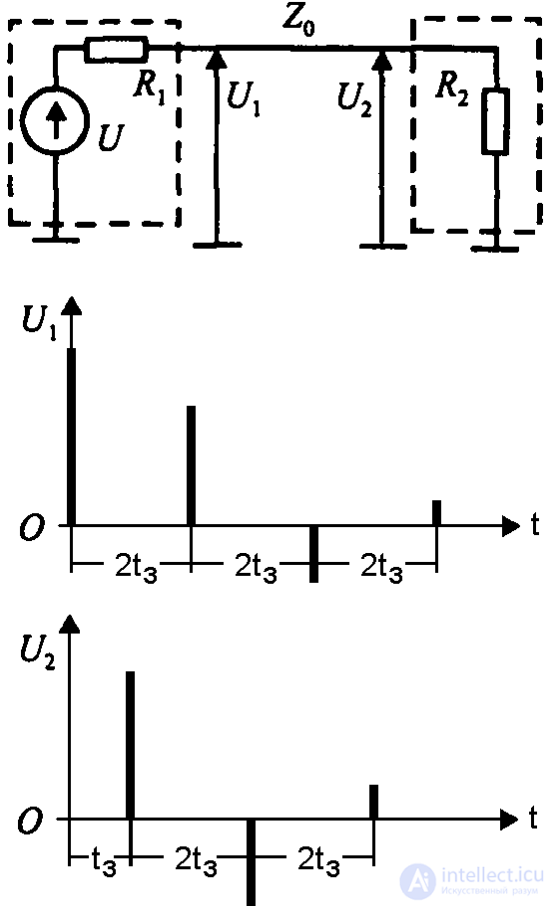
Fig. 5.1.4.
When transmitting signals over long lines, it is important to match the load resistance to the characteristic impedance of the line. In an unmatched line, a forward (incident) wave, which
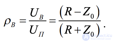
propagates from the beginning of the line to its end, is present simultaneously with a reverse wave reflected from the load, traveling from the end of the line to its beginning. The ratio of the amplitude
of the voltage UB reflected from the load R to the amplitude UP of the incident
wave is given by the reflection coefficient:
The reflected wave propagates from the end of the line to the beginning (with a certain loss of energy at Z0), and after a certain delay time
t reaches the beginning of the line and is likewise reflected from the output resistance of the signal source. At high frequencies the wave propagation velocity tends to a constant value
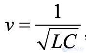 , and, accordingly,
 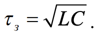 . At low frequencies, where the capacitive nature of the line predominates, the delay time can increase by a factor of 1.5-2.
If the resistances at the beginning and end of the line are respectively R1 and R2, and the ratio at the output holds as R1 and
r B2
of the line will respectively be 1
0 1 > >- r B and 2
0 1 < < r B .
Distortion of a pulse signal, when the duration of the transmitted pulse ty << tc
, as it travels along the TL is shown in Fig. 5.1.4. The signals on the graphs correspond to the instants they arrive at the input U1 and output U2
of the TL. Note the change in polarity of the reflected signals depending
on the ratio of the values R1 and R2 to
the value Z0. Thus, one pulse
entered the line, while at the input
loaded onto the line, the technical device with a period
of 2tc may end up with several pulses exceeding its triggering threshold.
Reducing or completely eliminating
reflections in long lines can
be achieved by matching them. A transmission line is considered matched if
the resistance it is loaded with is equal to
the characteristic impedance of the line, in which case the value r B2
becomes zero. It is also recommended to match the line to the signal source, if its
output resistance R1 is much smaller than Z0, which zeroes out the value r B1
. Matching is provided by introducing matching resistors Rc
at the inputs and outputs
of the TL. For signal sources with low output resistance, series
matching with the TL is used 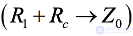 , while for signal receivers with high input
resistance, parallel matching is used 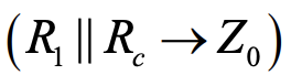 . With a larger number of
loads at the TL output, emitter followers are used for matching (Fig. 5.1.5).
When designing digital equipment,
the inputs of flip-flops, one-shots and registers are not recommended to be connected directly to long
lines. The absence of buffer stages, because of significant
capacitive loading and the presence of reflections,
will lead to unstable operation of the equipment. Schmitt triggers are usually used as buffer stages to restore pulse edges. Buffer stages are likewise recommended for matching coaxial cables with a
characteristic impedance of 50 Ω, in which case the cable output
is loaded with a resistance of 51 Ω.
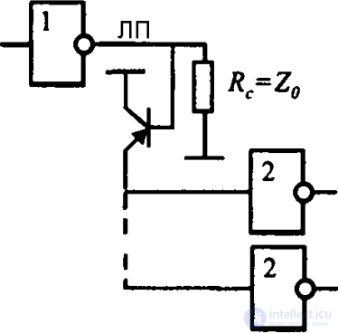
Fig. 5.1.5.
Depending on the specifics of the equipment being developed, microstrip and stripline printed conductors, twisted pair,
flat cable and coaxial cable are used as long lines. At a high level of electromagnetic interference external to the TL,
the use of coaxial cables and
twisted pairs is recommended, forming opposite-polarity signals on the two wires of the pair.
High-frequency alternating or pulsed current is distributed non-uniformly across the cross-section of a conductor, having its greatest density near its surface,
which is a result of the skin effect. The skin effect increases the
resistance of the conductor to alternating current. The influence of the skin effect shows up
as distortion of the edge and shape of the pulse, since different frequencies are attenuated differently in
the conductor material. To reduce the skin effect,
wire stranded from a large number of strands insulated from one another is used.
of one conductor.
To eliminate crosstalk, transmission lines are shielded. Using a TL with a shielding metal sheath is an effective way
to protect against the effects of electric and electromagnetic fields. Shields must be grounded with short wires of minimal inductive resistance or by
direct contact with the chassis of the instrument. The absence of grounding of TL shields does not eliminate capacitive coupling between the center conductors. If the current
flowing through the center conductor of the TL is equal to the return current through
its braid, then in the space surrounding the line, the electromagnetic field is absent.
The material of the current-carrying conductors of wires is copper and its
alloys. As equipment dimensions have decreased, and the lengths and diameters
of wiring wires have decreased, along with tightened requirements for mechanical actions, more and more
use is being found for copper alloys offering higher tensile strength
and flexibility, at a small cost in conductivity.
Wiring wires may be single-strand or multi-strand. High
flexibility, durability and reliability of the wire under conditions of shock and vibration is achieved by stranding several individual wires into a multi-strand construction. Industry produces multi-strand wire with 3, 7, 12, 17, 19, 27 and 37 round
strands. Multi-strand wire with a total cross-sectional area of the current-carrying strands equal to the cross-sectional area of a single wire has
a somewhat larger diameter and cost, both of which grow as the number of strands increases.
The mechanical strength of multi-strand wires is increased by incorporating a reinforcing central steel strand into the wire construction.
Protection against electrical short-circuiting of the wire to the product's chassis or to a neighboring wire is provided by applying an insulating coating to the current-carrying conductor. The material and construction of the insulation must ensure high values of electrical parameters (dielectric strength, insulation resistance, dielectric constant) during and after the application of external actions, as well as after prolonged
storage. A wide variety of insulating coating types currently exists.
Wire is selected based on the required operating conditions, current loading, permissible voltage drop, leakage current, and dielectric strength. Single-strand wires are recommended for use in stationary equipment not subject to shock and vibration. Increasing the number of wire strands improves its resistance to repeated flexing under
vibration conditions. Multi-strand wires are used in onboard equipment.
The following range of cross-sections for the current-carrying strands of wiring wires can be recommended: 0.03; 0.05; 0.08; 0.12; 0.20; 0.35; 0.50; 0.75; 1.0;
1.5; 2.5 mm2. The choice of wire diameter depends on the current flowing and the permissible overheating of the wire. The current density for different wire diameters at
long-term permissible current loads, causing the wire to overheat by 20 °C relative to the ambient temperature, is given in the table.
Permissible load currents for copper wires
| Electrical parameter | Diameter, mm | 0.25 | 0.35 | 0.5 | 0.7 | 0.9 | 1.1 | 1.4 | 1.6 | 1.8 | 2.5 |
|---|---|---|---|---|---|---|---|---|---|---|---|
| Current density, A/mm² | 14 | 13 | 12 | 10 | 10 | 10 | 9 | 9 | 8 | 8 | |
| Current, A | 0.7 | 1.3 | 2.5 | 4 | 7 | 10 | 14 | 17 | 20 | 30 |
Permissible load currents for copper wires. From the data in this table it follows that for smaller-diameter wires a higher current density occurs,
owing to more active heat exchange with the environment. The table below lists
the grades of commonly used wiring wires.
Grades of wiring wires
| Wiring wire | Grade | Temp., °C | Field of application |
|---|---|---|---|
| With fibrous and PVC insulation | MShV, MGShV, MGShVE, MGV, MGVE | -60 / +70 | Fixed intra- and inter-instrument wiring of equipment for field conditions |
| With PVC insulation | MGVL, PMV, PMOV, PMVG | -60 / +70 | Fixed wiring of low-current equipment |
| With lavsan (PET film) insulation, heat-resistant | MGTL, MGTLE | -60 / +150 | Fixed and flexible intra-instrument wiring |
| Small cross-sections | MGTF, MGSTF, MGTFE | -60 / +70 | Wiring of low-current equipment |
| With polyethylene insulation of increased heat resistance | PMP, PMPE, PMPL | -60 / +220 | Intra- and inter-instrument wiring |
A twisted pair is obtained by twisting two insulated conductors together with a certain
pitch. Twisting the conductors reduces electromagnetic coupling between circuits and increases their protection against mutual and
external interference. Thanks to the twisting of the conductors, instead of a single coupling loop, several small loops of equal area are formed, in which
the interference currents induced by an external electromagnetic field flow in opposite directions in the twisted pair and mutually cancel out.
For TLs with a conductor diameter of 0.9-1.2 mm, the twist pitch should be 100-300 mm,
for diameters of 0.3-0.8 mm the pitch is chosen within the range of 40-90 mm. For different twist
pitches, the interference attenuation coefficients have the following values:
Twist pitch, mm ............................ 100 75 50 25.
Attenuation coefficient, dB.........23 37 41 43.
The inductance of a twisted pair is lower than the inductance of an unbalanced
two-wire TL. The characteristic impedance of a twisted pair is calculated by the formula:
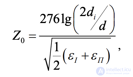
where ,
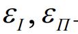 – relative dielectric constant of the air/insulation of the conductors,
d1 and d
– diameter of the wire with insulation and without insulation.
A twisted pair provides good protection of signals from electromagnetic interference up to a frequency of 100 kHz and satisfactory protection up to a frequency of 10 MHz, while guaranteeing
constancy of the characteristic impedance.
Improved noise immunity of the TL in high-frequency equipment is provided by the use of coaxial cables.
A coaxial cable is a two-conductor TL consisting of an outer tubular conductor (braid), inside which is coaxially located
a conductor, separated from the braid by a dielectric medium.
Industry produces coaxial cables with a characteristic impedance from 50
to 3200 Ω and a nominal diameter from 0.6 to 120 mm. The cable grade designation indicates
its type, characteristic impedance, diameter, insulation group and heat resistance, and the sequential design number. For example, the cable grade RK-50-4-11 means that this is a
radio-frequency cable with a characteristic impedance of 50 Ω, a diameter of 4 mm, ordinary
heat resistance 1, with a sequential design number of 1.
Coaxial cable is used to transmit various signals over a wide frequency range. The constancy of its electrical parameters and its
high level of protection from electric and electromagnetic fields account for the
widespread use of coaxial cables.
In inter-instrument switching of low-frequency equipment, the braid of the
coaxial cable is grounded at one end via the terminals of an electrical connector, to prevent the formation of ground loops. The braid of the cable in high-frequency equipment is connected to the zero-potential line at
several points at an interval of 0.25λ, where λ is the wavelength of the signal at the highest frequency. When significant currents flow through the zero-potential line,
multipoint grounding of the cable loses its effectiveness. The table below lists the main grades of coaxial cables.
| Cable | Grade | Temp., °C | Field of application |
|---|---|---|---|
| Radio-frequency with solid insulation | RK-50-2, RK-75-4, RK-100-7, RK-50-9, RK-75-9, RS-400-7, RS-1600-7 | -60 / +70 | Stationary and mobile equipment |
| Coiled | — | -60 / +85 | Pulse signal delay elements |
| Radio-frequency heat-resistant, compact | RKT-72, RKT-73 | -60 / +125 | Intra-unit wiring |
The presence of a coaxial cable's braid leads to a sharp increase in the capacitance between the center conductor and the shield, which must necessarily
be taken into account at the circuit design stage. Coaxial cables have significant
dimensions, are complex to install, and are recommended for use in intra-module and inter-module switching.

Comments