Lecture
Existing radio monitoring systems.
Radio frequency information transmission systems include all means of radio communication that use radio air as a transmission medium. We will single out among them the following main types of interest to us: cellular mobile communication systems; radio relay and satellite systems.
Since, in principle, the structural diagrams of these systems are almost the same and include channel-forming equipment, antenna systems, repeaters, and radio broadcasting, the measurement technologies for these types are almost the same. Differences can occur only due to differences in the radio frequencies used and radio propagation conditions. While for cellular and radio-relay transmission systems, the evaluation of attenuation parameters associated with attenuation in multipath propagation of radio waves is a significant factor, for satellite communication systems, signal propagation delay is of great importance, and the effect of Doppler frequency shift is more significant for satellite radio communication systems.
The basis of radio frequency measurements are:
- measurements of the radio, associated with the analysis of the electromagnetic environment in the whole spectrum used by the transmission system;
- measurements of repeaters (in cellular networks, in radio-relay and satellite communication systems);
- studies of the passage of signals through communication channels.
The construction of radio monitoring systems is a very important issue that requires agreement at the intergovernmental level and implementation within the country.
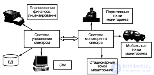
In fig. 7.14 shows the structure of the national monitoring system [7.10], the purpose of the subsystems of which are as follows.

Fig. 7.14. The structure of the national monitoring system.
The spectrum management subsystem should solve the following tasks:
1) ensuring planning of the use of a radio frequency resource;
2) the creation and continuous updating of databases for the right to use resources;
3) management of financial receipts for the use of a radio frequency resource.
The spectrum management subsystem includes a single national database.
(BD) of the state of the electromagnetic environment by region, a database of licenses (issued to operators), as well as the workplaces of operators of the center of the control of the electromagnetic environment. Thus, the spectrum management subsystem solves organizational and legal issues of monitoring the radio frequency resource of any country.
The spectrum monitoring subsystem solves technical problems, which include:
1) search for possible sources and causes of signal interference in all used frequency bands;
2) verification of compliance of signals with existing standards and licenses;
3) identifying illegal transmitters and sources of information.
The spectrum monitoring subsystem includes fixed, mobile and portable spectrum monitoring points. These points are combined through a data transmission network, and information is concentrated in information processing centers, from which they are then transmitted to the main information processing center for final processing, storage, planning and optimization of the use of a radio frequency resource.
Thus, national monitoring systems are individual for each country. Therefore, it is almost impossible to compare the technical characteristics of these systems. It can only be stated that such systems are created and standardized by leading firms Nokia, Siemens, Cisco, Ericsson, Hewlett-Packard, etc.
Trends in the use of radio frequency resources and requirements for national radio broadcast control systems include [7.10]:
- increase in loading of VHF / UHF ranges; an increase in the number of signals when mobile monitoring of the VHF / UHF band is necessary, since the systems have a limited coverage area;
- the use of digital modulation methods [7.10], if necessary, the use of digital radio receivers;
- the deployment of national and private radio networks, if necessary, to reduce interference from the networks of various operators and the illegal use of the radio frequency spectrum;
- increase in the number of licenses, slowing down the licensing process in the transition to licensing technology based on distributed databases.
The following by the level of the radio monitoring system - regional and local significance, differ from the national system only by the size of the data transmission network. Radio monitoring systems of this level are built on the principle of radial topology with a data processing center and associated stationary and mobile spectrum monitoring points. Binding to geographic coordinates at monitoring points, as well as in national radio monitoring systems, can be performed by satellite systems (for example, using the GPS —Global Position System).
In world practice, the experience of using regional control systems for controlling the use of a radio frequency resource has become widespread. Radio monitoring systems for using a radio frequency resource include systems for analyzing radio coverage zones in cellular mobile networks. Operators of wireless radio networks (cellular mobile communications, trunked networks, etc.) also use systems to analyze the load of the allocated radio frequency resource, as well as to analyze zones of reliable reception of signals from base stations of the cellular network. Typically, such systems are characterized by lower functionality of radio measurements and significantly lower cost. For effective operation of regional control systems, it is necessary to analyze the spectrum in a controlled radio frequency range, as well as to analyze the reception / transmission zones, for example, using selective receivers tuned to the operating range. Currently, the functionality of systems for analyzing zones of reliable reception is growing. The composition of such systems include spectrum analyzers. As an example, we mention a specialized system - the Illuminator model, which implements the measurement and analysis of radio coverage zones. In this system, a scanning radio receiver and processing systems based on portable PCs are used to measure and control the radio spectrum and assess the radio coverage area.
In addition to systems of special, regional and local significance, local-purpose radio monitoring systems are used for measurements and radio monitoring. In the monitoring systems of the local electromagnetic environment, instruments are used, usually spectrum analyzers with the required set of antennas, to determine the parameters of the radio when placing sources of radio signals. Such systems are usually used to analyze base stations BTS of cellular mobile communication systems before installation, radio relay stations, satellite ground stations, etc.
The main tasks of the local analysis of the electromagnetic environment are:
1) determination of compliance of the allocated radio frequency resource with specified specifications;
2) optimization of the placement of radio sources in a given territory;
3) the localization of possible interference and sources of signal interference, which lead to disruptions of radio communication.
Local monitoring systems (radio monitoring) can be used both at the stages of cellular network deployment and at the operation stage of cellular systems for monitoring the use of the allocated resource and analyzing the electromagnetic environment in the operating range of the system.
The basis of the local radio monitoring system consists of spectrum analyzers:
- high-precision stationary analyzers (for example, firms Anritsu, HP, Advantest), used in the junction stations of radio communication systems,
- portable analyzers used for tuning antennas of subscriber terminals of satellite communication systems, radio communication systems, as well as for indication and coarse localization of interference sources and interference, having low accuracy, low dynamic range and narrow spectrum.
Radio frequency path in information transmission systems.
As is known, a typical radio frequency path includes the following components (more precisely, channel-forming devices): sources and receivers of information, which, as a rule, are devices for transmitting and receiving analog information (for example, voice signals, etc.); coders / decoders (codecs) - devices that convert digital signals into codewords; modems (modulators / demodulators); IF filters (intermediate frequency); converters; RF (radio frequency) filters; antenna devices, as well as the propagation medium (radio).
The main parameters of the radio frequency path include:
1) C / N (signal / noise) and SI (signal / interference) ratios;
2) the bit error parameter is BER, which depends on the C / N parameter;
3) power levels within the service area;
4) attenuation of radio signals with multipath propagation.
Considering these parameters, we can distinguish the corresponding groups of measurements of sections of the radio frequency path:
- measurement and control of the dependence of the bit error parameter BER on the signal-to-noise ratio;
- measurement and control of the power levels of radio signals at arbitrary points in the radio coverage zone, taking into account multipath propagation of radio waves;
- measurements of the level of communication quality degradation in radio frequency transmission systems, which may be caused by the phase noise of the transmitting path and the thermal noise of the receiver (the effect of these factors is so great that noise measurements are usually allocated to a separate measurement class);
- determination of the probability of intersymbol interference, which requires an analysis of the IF and RF filters;
- control of possible malfunctions of modems, leading to the need to measure modulation parameters;
- consideration of the possibility of nonlinearity in amplifying elements, which requires monitoring amplifiers and measuring the characteristics of the amplification of these elements, etc.
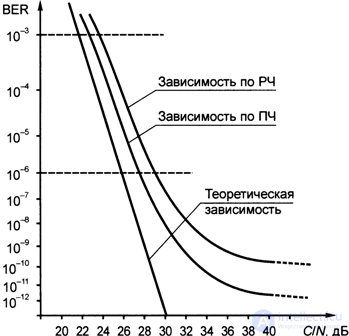
To evaluate the effectiveness of the digital radio frequency information transmission system, as is known, it is necessary to know the dependence of the BER parameter on the C / N ratio - BER (C / N). This parameter is a characteristic of the system, since it does not depend on the parameters of the working signal, but depends only on the equipment of the radio path and its location. The dependence BER = f (C / N) is a constant characteristic of each specific path, although it can vary significantly for different paths. This is due to the influence of parameters associated with the installation and configuration of equipment for the digital transmission system. Knowing the dependence of BER on the signal-to-noise ratio and measuring the signal parameters in the radio frequency path, it is possible to estimate the contribution of certain sections and circuits to the overall deterioration in the quality of the information transmission system. When measuring radio frequency transmission systems and digital radio channels of radio communication networks, knowing the dependence of the AEASH / N) allows us to characterize the installed system sufficiently to suit the installation.
Let us consider the C / N and SI ratios used in practice and their connection with the signal power per bit of information, as well as the THz / N function for different values of the product of a band by the duration of one bit - TTV.
Parameters characterizing the level of noise in measurements in digital radio channels.
When designing cellular systems and measurements in digital radio channels, the following basic parameters are used:
- the ratio of the average power of the carrier signal to the average noise power (this parameter most simply represents the signal-to-noise ratio);
- for a number of measurements, the C / N parameter is not suitable, since it is associated with the measurement of average powers, including the noise power in a certain frequency range; To exclude the range factor in noise measurement, the parameter C / No is used, which is the ratio of the carrier signal power to noise power normalized to the 1 Hz band;
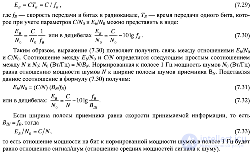
- for the characteristic of digital radio frequency transmission systems, the third parameter is used - Еb / Nq (the ratio of the required power per bit (Еб) to the spectral density of the noise L0, normalized in the 1 Hz band), associated with the ratio C / Nq, normalized by the data rate in the channel.
Consider the relations existing between the above parameters [7.1].
1) The energy per bit Eb is related to the parameter C (average power of the carrier signal) by a simple relation:

Energy efficiency and the characteristic of the probability of errors in bits when exposed to additive white Gaussian noise (ABGN)
The energy efficiency of various types of modulation is determined using the following expressions [7.1]:
RE = BER = f! (C / N) or PE = BER = f2 (Eb / No), (7.34)
where PE is the probability of error, BER is the bit error rate, which are functions of the C / N or Eb / N0 ratio. (7.35)
The higher the probability of error, the lower the energy efficiency, since the transmitted signal power is “wasted” in vain when there is a large amount of distorted data, the lower PE = BER, the higher the energy efficiency.
For GMSK, the probability of a BER error with non-linear amplification when subjected to additive white Gaussian noise (ABGN) is: when BNTB = 0.3 for Eb / N0 = 12 dB, PE = 2 * 10 “5, for Eb / No = 10 dB, PE = 3-KG4, with Eb / No = 8 dB, PE = 21 (G3.
For MSK, when BNTB = 00 with E, JN {] = 10 dB, PE = 2-1 () \ with Eb / Nq = 8 dB, PE = 6-10-4, with Eb / No = 6 dB, PE = 410 ~ 3.
It should be noted that in the GSM standard, the equality BNTB = 0.3 leads to an increase in the required C / I ratio while increasing the influence of radio wave propagation conditions and equipment imperfection. In this case, PE = Yu “3 with C / N = 30 dB, with Eb / N0 = (C / N) x (BN / fB) = = C / Nx0.3 = 9 dB.
The practical dependence BER = f (C / N) is shown in Fig. 7.15.

Fig. 7.15. Practical dependency BER (C / N)
Comments
To leave a comment
GSM Basics
Terms: GSM Basics