Lecture
The widespread use in the cellular mobile communication systems of the radio waves of the UHF band (300 ... 3000 MHz) naturally distinguishes a certain range of possible antenna systems used at base and mobile stations. First of all, these are dipole antennas of various designs.
The complex propagation conditions of radio waves in cellular mobile communication systems, associated with their repeated reflection, scattering, lead to the fact that the laws that are valid for systems operating in direct visibility conditions become unfair, and the directional properties of antennas that were fair to the conditions of free space, vary considerably. Therefore, the design of antennas in mobile communication systems takes into account the statistical characteristics of the environment in which these antennas are used, that is, urban conditions, vegetation, hills, etc.
We will use the results of scientific research in this area [3.1-3.3, 3.5, 3.7, 3.8] and consider specifically the antennas widely used in mobile stations (base station antennas will be discussed below in Chapter 5).
Features of the operation of mobile phones lead to features in the requirements for antennas used in them:
- very small size;
- relatively large operating frequency band (at frequencies of 900.1800 and 1900 MHz);
- efficiency in the transmission and reception of radio waves with different spatial orientations of mobile phones, taking into account multipath propagation of radio waves within a cell;
- high mechanical properties (for example, impact resistance).
The following types have become widely used as antennas in cellular mobile phones [3.3]:
- symmetrical vibrator with a coaxial screen in the central part (sleeve dipole);
- helical antenna;
- quarter-wave asymmetric dipole (quarter wavelength whip (monopole) antenna);
- combined spiral antenna (diversity helical antenna system).
Symmetrical vibrator with coaxial screen in the central part
In fig. 3.4 shows a mobile phone with an antenna representing a symmetrical vibrator with a coaxial screen in the central part (sleeve dipole) and operating in the frequency range (800 ... .900) MHz.

This is essentially a half-wave dipole fed from one end by means of a coaxial line. The antenna constructively represents a half-wave vibrator of different shoulders:
- the upper arm, lx = X / 4 long, is formed from a thin central core of a coaxial feeder;
- the lower arm, long / 2 ^ X / 4, is formed from a metal coupling (metal sleeve), a dielectric filler (dielectric insert) with a dielectric constant of e2 of small size and a coaxial feeder.
The length / 2 of the coupling, equal to X / 4, makes it possible to create a short circuit in section A-A, since in
B-ZBXb b = jZ0tgkl = / Z0tg ^ y => oo,
which causes in section А-А on / 2 = Х / 4 the value Zbxa-a => 0, that is, it short-circuits the metal coupling on the braid of the coaxial line in section А-А. Thus, a half-wave (in the real case - mixed shoulders) radiator with a current ix (t) is formed. Diverse X / 2
vibrator allows you to extend the range of the emitted and received frequencies. In fig. 3.5, and shows the radiation pattern of the vibrator in the vertical plane at the resonance frequency.
When changing the frequency / = / about ± 5% / 0, that is, 5% of the carrier / 0, the directivity pattern changes (Fig. 3.5, b), while the direction of the main lobe descends.
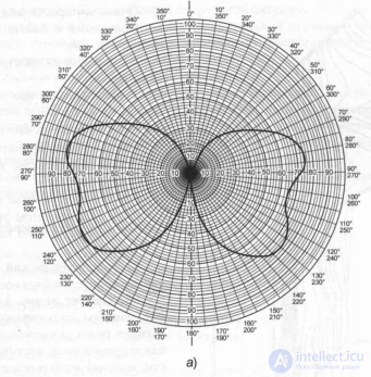
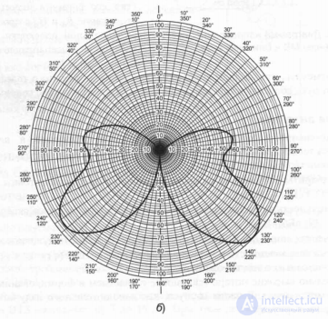
Fig. 3.5. Direction pattern in the vertical plane of a symmetrical vibrator with a coaxial screen: a) at the resonance frequency; b) when the frequency changes by 5% of the carrier f0
The view of the near zone, studied in [3.3] and shown in fig. 3.6.
As follows from the spatial pattern of Fig. 3.6:
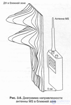
1) there are two maxima in the change of £ 0 (g, 0, f):
- in the region of a thin radiating conductor (approximately 1 \ ~ 1 \ / 2), while £ e (f) is non-directional;
- in the area of the coupling almost on / i - / 2/2, while the level £ e (g, 0, f) is close to the level of the upper conductor;
2) there is a sharp decline in £ e (r, 0, f) in the area of the mobile phone case.
As follows from fig. 3.4 and 3.5, changing the frequency of the emitted / received signal dramatically affects the radiation pattern in the vertical plane, changing the direction of the main lobe, its shape, and therefore the distribution of Eq and Yaf in space as a whole. In the meridian plane, this antenna is isotropic (omnidirectional), with £ e (φ) = const, jF (0) = 1.
It should be noted that the subscriber’s arm and the position of the antenna relative to its head strongly influence the directional pattern of a mobile phone.
Spiral antennas.
Spiral antennas have also found widespread use as mobile phone antennas in the 800 ... 900 MHz range.
Their advantages include:
- small dimensions (the physical length of the shortened spiral antenna / = X / 12, that is, at X = 33.3 cm, / -2.8 cm);
- sensitivity in the mode of reception according to the directivity of the electric field: E - (21 ... .29) dB / µV / m;
- electrical length / Е = Х / 2, that is, corresponds to the length of a half-wave dipole;
- radiation pattern in the meridional plane ^ P (f) = 1.
The disadvantages of such antennas include:
- relatively high losses (associated with participation in the formation of the directional properties of the metal part of the body, as an additional radiator, and losses in the dielectric of the body);
- change of the radiation pattern with frequency;
- fulfillment of the requirement that the metal part of the body (radio case) has a length of 1 ~ X / 4, since at / »X / A the directivity pattern changes dramatically.
Consider briefly the features of such a spiral antenna.
The levels of field distribution in the near zone of the spiral antenna and the metal case of the mobile phone change analogously to the distribution shown in Fig. 3.6, that is, at a distance of r = 5 cm, the following are observed:
- high level of radiation by the antenna itself;
- a fairly high level of radiation of the mobile phone casing.
As noted in [3.3], measurements carried out to determine the level of radiation of mobile phones using shortened spiral antennas showed that compared to a conventional half-wave vibrator radiating in free space, the radiation level of shortened antennas is 10 ... 12 dB lower .
The use of a shock-resistant radiotransparent coating allows creating conditions for highly reliable operation of mobile phones.
Combined Spiral Antenna.
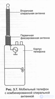 An alternative version of the shortened spiral antenna was designed as a combined spiral antenna fig. 3.7, which is the following construct [3.3]:
- primary fixed helix (primary fixed antenna), l = 2 cm long and corresponding to X / 4 in electrical length;
- a secondary spiral antenna on a dielectric rod (collapsible secondary helican antenna on dielectric rod), length l2 = 10 cm, corresponding to X / 2 for electrical length;
- this antenna can be removable or fold out of the phone.
When the secondary antenna is extended, it becomes the main emitter, as it is free from losses caused by the hand of the subscriber holding the phone body.
.

Comments
To leave a comment
GSM Basics
Terms: GSM Basics