
Lecture
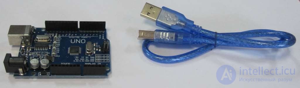
To install the software and connect an Arduino UNO R3 controller to a computer, you need:
The board can draw power from the computer's USB port, so an external power supply is not required.
Installing the Arduino IDE integrated development environment.
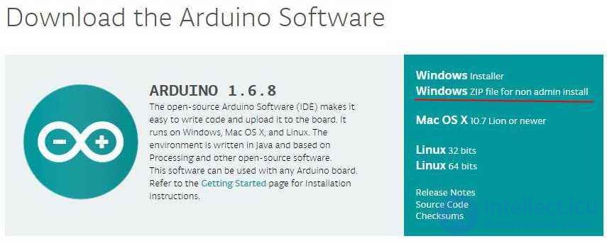
First of all, you need to download the latest version of the program. You can download the ZIP archive from the official Arduino support website via this link. Select the line for the operating system you need – Windows ZIP file...
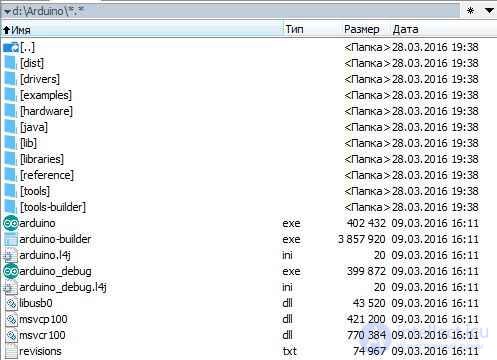
Create a folder, for example Arduino, and unpack the zip file into it.
Connecting the Arduino board.
Connect the board to the computer using the USB cable. An LED (labelled ON) should light up, indicating that power is reaching the board.
Installing the driver.
I know of Arduino UNO R3 boards using the following as the USB-UART bridge
The driver installation process differs between these variants.
Installing the driver for an ARDUINO UNO with an ATmega16U2 interface converter.
Once the board is connected to the computer, Windows will start installing the driver itself. After a while, a message about a failed attempt will appear.
The driver must be installed manually. To do this, go to Start –> Control Panel –> System –> Device Manager.
In the Ports (COM and LPT) section there should be an Arduino UNO device with a yellow warning icon.
Right-click the icon.
Select Update driver.
Next, Browse my computer for drivers.
Manually specify the location of the driver. The ArduinoUNO.inf file is located in the Drivers folder inside the folder where the archive was unpacked.
A new virtual COM port appears in the Ports (COM and LPT) section. Remember its number.
Installing the driver for an ARDUINO UNO with a CH340G interface converter (Chinese clone).
Once the board is connected to the computer, Windows will start installing the driver itself.
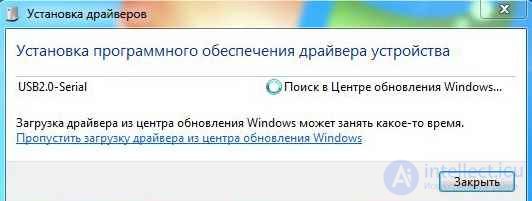
After a while, a message about a failed attempt will appear.
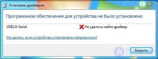
The driver must be installed manually. To do this, go to Start –> Control Panel –> System –> Device Manager.
A new device, USB2.0-Serial, appears with a yellow warning icon.
Run the ch341ser.exe installer.
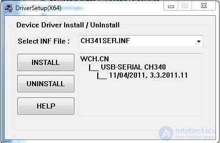
Select INSTALL.
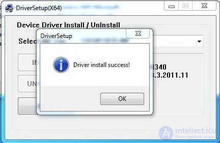
Wait for the message about successful installation.
A new device, USB-SERIAL CH340, appears in Device Manager.
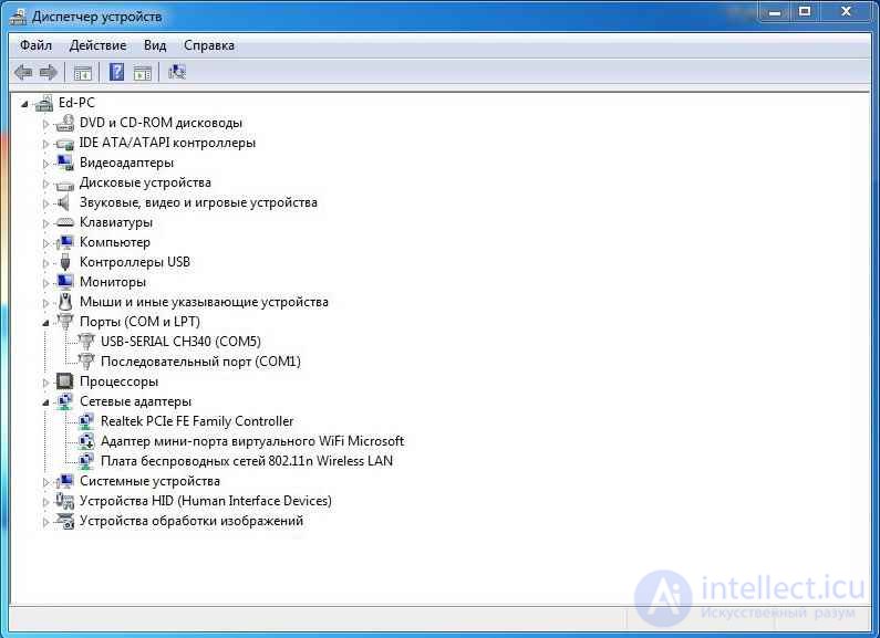
Remember the COM port number.
Starting the Arduino IDE integrated development environment.
Run the arduino.exe file.
Select the Arduino board type: Tools -> Board -> Arduino UNO.
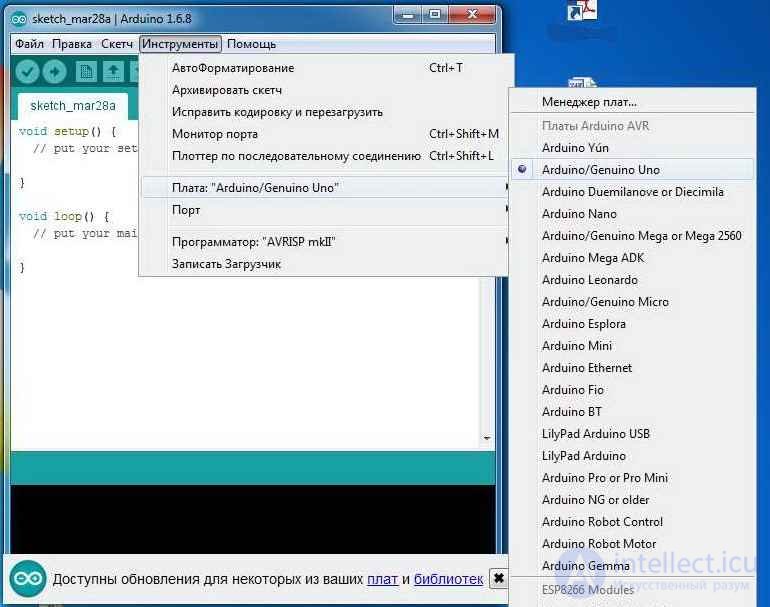
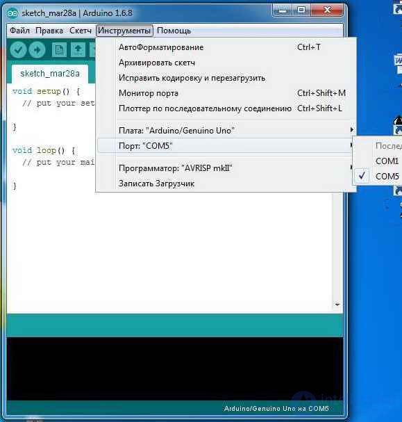
You need to specify the COM port number: Tools -> Port.
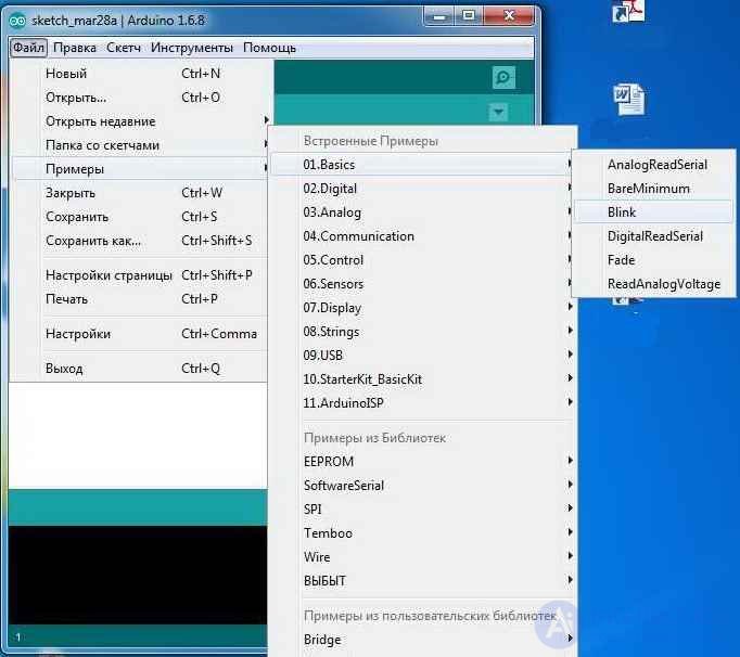
To check that the system works, you can run the first sketch – a blinking LED. To do this: File -> Examples -> 01.Basics -> Blink.
Click the Upload button.
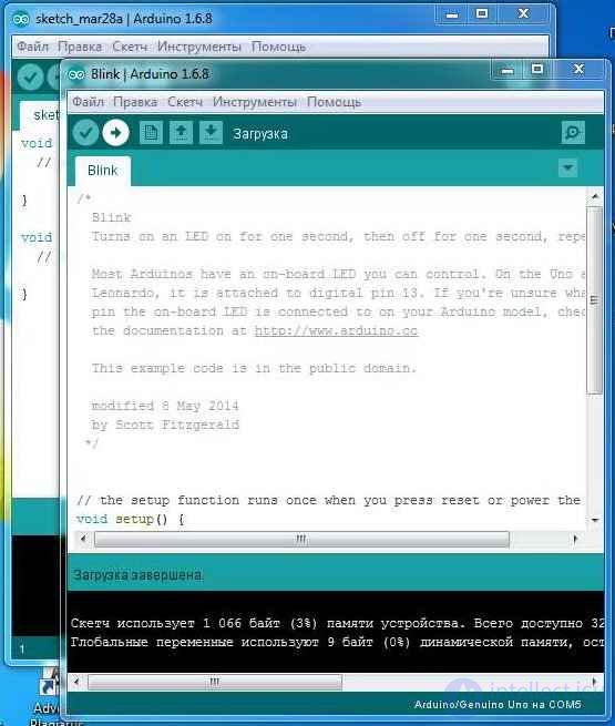
Wait for the program to upload, and the LED on the board, marked with the letter L, will start blinking about once a second. This means everything was done correctly.
In the next lesson we will gain minimal knowledge of the programming language for Arduino - the C++ language.
this is minimal information. A description of pointers, classes, string variables and so on will be given in later lessons. If something turns out to be unclear, don't worry. There will be plenty of examples and explanations in later lessons.
Structure of an Arduino program.
The structure of an Arduino program is quite simple, and in its minimal form consists of two parts, setup() and loop().
void setup() {
// code executed once when the program starts
}
void loop() {
// main code, executed in a loop
}
The setup() function is executed once, when the controller is powered on or reset. It is normally used for the initial setup of variables and registers. The function must be present in the program even if there is nothing in it.
After setup() completes, control passes to the loop() function. It executes, in an infinite loop, the commands written in its body (between the curly braces). It is these commands that actually perform all the controller's algorithmic actions.
Initial rules of C language syntax.
; semicolon Expressions may contain any number of spaces and line breaks. The end of an expression is marked by a”semicolon” character.
z = x + y;
z= x
+ y;
{ } curly braces define the block of a function or of expressions. For example, in the setup() and loop() functions.
/* … */ comment block, must be closed.
/* this is a comment block */
// single-line comment, does not need to be closed, it applies to the end of the line.
// this is one line of comment
Variables and data types.
A variable is a memory cell in which information is stored. A program uses variables to store intermediate calculation data. Data of various formats and various bit widths can be used for calculations, so variables in the C language have the following types.
| Data type | Bit width, bits | Number range |
| boolean | 8 | true, false |
| char | 8 | -128 … 127 |
| unsigned char | 8 | 0 … 255 |
| byte | 8 | 0 … 255 |
| int | 16 | -32768 … 32767 |
| unsigned int | 16 | 0 … 65535 |
| word | 16 | 0 … 65535 |
| long | 32 | -2147483648 … 2147483647 |
| unsigned long | 32 | 0 … 4294967295 |
| short | 16 | -32768 … 32767 |
| float | 32 | -3.4028235+38 … 3.4028235+38 |
| double | 32 | -3.4028235+38 … 3.4028235+38 |
Data types are chosen based on the required calculation precision, data formats, and so on. For example, you should not choose the long type for a counter that counts up to 100. It will work, but the operation will use more data and program memory and take more time.
Declaring variables.
You specify the data type, and then the variable name.
int x; // declaration of a variable named x of type int
float widthBox; // declaration of a variable named widthBox of type float
All variables must be declared before they are used.
A variable can be declared in any part of the program, but this determines which blocks of the program can use it. In other words, variables have scope.
int mode; // variable available to all functions
void setup() {
// empty block, no initial setup required
}
void loop() {
long count; // the count variable is available only inside the loop() function
for ( int i=0; i < 10;) // the variable i is available only inside the loop
{
i++;
}
}
When declaring a variable, you can set its initial value (initialize it).
int x = 0; // variable x is declared with an initial value of 0
char d = ‘a’; // variable d is declared with an initial value equal to the code of the character”a”
When performing arithmetic operations with different data types, automatic type conversion occurs. But it is better to always use explicit conversion.
int x; // int variable
char y; // char variable
int z; // int variable
z = x + (int) y; // variable y is explicitly converted to int
Arithmetic operations.
| = | assignment |
| + | addition |
| - | subtraction |
| * | multiplication |
| / | division |
| % | remainder of division |
Relational operations.
| == | equal to |
| != | not equal to |
| < | less than |
| > | greater than |
| <= | less than or equal to |
| >= | greater than or equal to |
Logical operations.
| && | logical AND |
| || | logical OR |
| ! | logical NOT |
Pointer operations.
| * | indirect addressing |
| & | getting the address of a variable |
Bitwise operations.
| & | AND |
| | | OR |
| ^ | EXCLUSIVE OR |
| ~ | INVERSION |
| << | SHIFT LEFT |
| >> | SHIFT RIGHT |
Compound assignment operations.
| ++ | + 1 to the variable |
| -- | - 1 to the variable |
| += | addition |
| -= | subtraction |
| *= | multiplication |
| /= | division |
| %= | remainder of division |
| &= | bitwise AND |
| |= | bitwise OR |
Choosing between options, program control.
The IF statement checks the condition in parentheses and executes the following expression or block in curly braces if the condition is true.
if (x == 5) // if x=5, then z=0 is executed
z=0;
if (x > 5) // if x > 5, the block z=0, y=8 is executed;
{ z=0; y=8; }
IF … ELSE lets you choose between two options.
if (x > 5) // if x > 5, the block z=0, y=8 is executed;
{
z=0;
y=8;
}
else // otherwise this block is executed
{
z=0;
y=0;
}
ELSE IF – lets you make a multi-way choice
if (x > 5) // if x > 5, the block z=0, y=8 is executed;
{
z=0;
y=8;
}
else if (x > 20) // if x > 20, this block is executed
{
}
else // otherwise this block is executed
{
z=0;
y=0;
}
SWITCH CASE - a multi-way choice. Lets you compare a variable (x in the example) against several constants (5 and 10 in the example) and execute the block where the variable equals the constant.
switch (x) {
case 5:
// code executed if x = 5
break;
case 10:
// code executed if x = 10
break;
default:
// code executed if none of the previous values matched
break;
}
The FOR loop. This construct lets you organize loops with a set number of iterations. The syntax looks like this:
for ( action before the loop starts;
loop continuation condition;
action at the end of each iteration ) {
// loop body code
}
Example of a loop with 100 iterations.
for ( i=0; i < 100; i++ ) // initial value 0, final value 99, step 1
{
sum = sum + I;
}
The WHILE loop. This statement lets you organize loops with the construct:
while ( expression )
{
// loop body code
}
The loop executes for as long as the expression in parentheses is true. Example of a loop with 10 iterations.
x = 0;
while ( x < 10 )
{
// loop body code
x++;
}
DO WHILE – a loop with the condition checked at the exit.
do
{
// loop body code
} while ( expression );
The loop executes while the expression is true.
BREAK – the loop exit statement. Used to interrupt the execution of for, while, and do while loops.
x = 0;
while ( x < 10 )
{
if ( z > 20 ) break; // if z > 20, exit the loop
// loop body code
x++;
}
GOTO – the unconditional jump statement.
goto metka1; // jump to metka1
………………
metka1:
CONTINUE - skips the statements up to the end of the loop body.
x = 0;
while ( x < 10 )
{
// loop body code
if ( z > 20 ) continue; // if z > 20, return to the start of the loop body
// loop body code
x++;
}
Arrays.
An array is a memory area where several variables are stored sequentially.
An array is declared like this.
int ages[10]; // an array of 10 int variables
float weight[100]; // an array of 100 float variables
Arrays can be initialized at the point of declaration:
int ages[10] = { 23, 54, 34, 24, 45, 56, 23, 23, 27, 28};
Array elements are accessed like this:
x = ages[5]; // x is assigned the value from element 5 of the array.
ages[9] = 32; // element 9 of the array is set to the value 32
Array element numbering always starts from zero.
Functions.
Functions let you perform the same actions with different data. A function has:
A user-defined function is described outside the setup() and loop() functions.
void setup() {
// code executed once when the program starts
}
void loop() {
// main code, executed in a loop
}
// declaration of a user-defined function named functionName
type functionName( type argument1, type argument1, …, type argument)
{
// function body
return();
}
Example of a function that calculates the sum of the squares of two arguments.
int sumQwadr (int x, int y)
{
return( x* x + y*y);
}
The function is called like this:
d= 2; b= 3;
z= sumQwadr(d, b); // z will hold the sum of the squares of variables d and b
Functions can be built-in, user-defined, or included from a library.
That was very brief, but this information should be enough to start writing programs in C for Arduino systems.
The last thing I want to talk about in this lesson is how C programs are conventionally formatted. I think if you are reading this lesson for the first time, it is worth skipping this section and coming back to it later, when you have something to format.
Recommendations for formatting programs in the C language.
The main goal of external program formatting is to improve program readability and reduce the number of formal errors. So, in order to achieve this goal, it is perfectly fine to break all of these recommendations.
Names in the C language.
Names representing data types should be written in mixed case. The first letter of the name should be capitalized (upper case).
Signal, TimeCount
Variables should be written as names in mixed case, with the first letter in lower case.
signal, timeCount
Constants should be written in upper case. An underscore is used as the separator.
MAX_TEMP, RED
Methods and functions should be named with verbs written in mixed case, with the first letter in lower case.
getTime, setTime
More on the remaining formalities in later lessons, as needed.
In the next lesson we will write our first program, and learn to read data from digital ports and control their state.
03.04.2016 Author: EDUARD
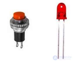
In this lesson we will write our first program, and learn to read the value of digital inputs and set the state of outputs. We will implement control of such simple elements as a button and an LED.
Previous lesson List of lessons Next lesson
The first program must control an LED using a button:
Connecting the button and LED to the Arduino board.
The Arduino UNO controller has 14 digital pins for connecting to external elements. Each pin can be defined by the program as an input or an output.
A digital output has only two states, high and low. The high state corresponds to an output voltage of about 5 V, the low state to 0 V. The output allows a load current of up to 40 mA to be connected.
When a pin is defined as an input, reading its state lets you determine the voltage level at the input. At a voltage close to 5 V (in practice, more than 3 V) a high state will be read, corresponding to the constant HIGH. At a voltage close to 0 (less than 1.5 V) a low state will be read, or the constant LOW.
We must connect the LED to a pin defined as an output, while the button is connected to a pin in input mode.
The LED is connected through a current-limiting resistor. Here is a typical circuit.
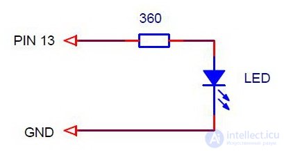
The resistor is calculated using the formula I = Uoutput – ULED drop / R.
Uoutput = 5 V, ULED drop can be taken as 1.5 V (a more precise value is given in the datasheet). This means that in our circuit the current through the LED is set at a level of 10 mA.
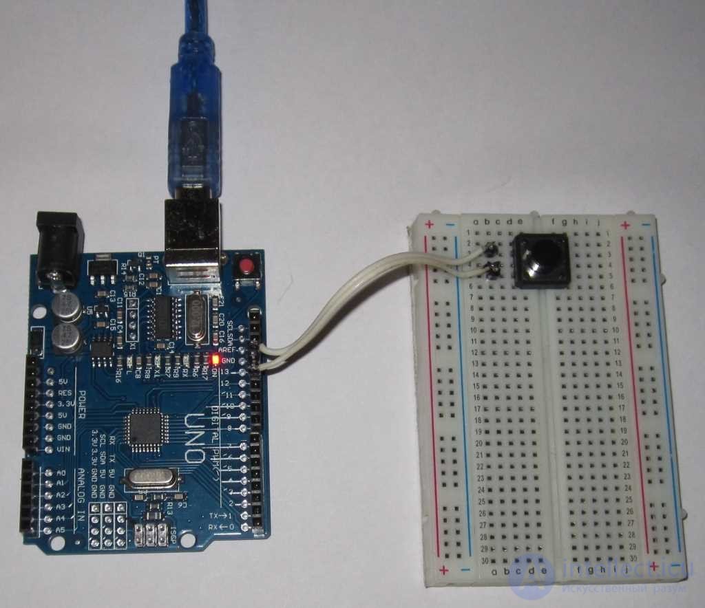
You can choose any pin, but for simplicity of wiring I suggest using the LED mounted on the board – the very one that blinked in the first test example. It is connected to digital pin 13. In this case there is no need to connect an additional LED to the board.
We connect the button to any other pin, for example, 12. The hardware part of the button-connection circuit must provide voltage levels of 0 V when the button is pressed and 5 V when it is released. This can be done with a simple circuit.
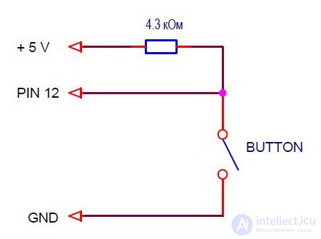
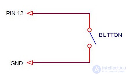
When the button is released, the resistor pulls the pin up to 5 V, and when it is pressed, the input is shorted to ground. I'll give recommendations for choosing the resistor in the final lesson on buttons. For now, let me suggest another option. Every pin on the board has an internal resistor inside the controller, connected to 5 V. These can be turned on or off for each pin by software. The resistance of these resistors is around 20-50 kOhm. That's too much for real-world circuits, but for our program and a button placed close to the controller, it's quite acceptable.
As a result, the connection diagram will look like this.
The button can be soldered to a connector with wires. I mounted mine on a breadboard without soldering. I bought it specifically to demonstrate these lessons.
Input/output control functions.
The Arduino system provides 3 built-in functions for working with digital pins. They let you set a pin's mode, read a pin, or set a pin to a given state. To define pin states, these functions use the constants HIGH and LOW, which correspond to a high and a low signal level.
pinMode(pin, mode)
Sets the pin's mode (input or output).
Arguments: pin and mode.
| mode = INPUT | pin is defined as an input, pull-up resistor disabled |
| mode = INPUT_PULLUP | pin is defined as an input, pull-up resistor enabled |
| mode = OUTPUT | pin is defined as an output |
The function returns nothing.
digitalWrite(pin, value)
Sets the output state (high or low).
Arguments pin and value:
| value = LOW | sets the output to a low state |
| value = HIGH | sets the output to a high state |
The function returns nothing.
digitalRead(pin)
Reads the input state.
Arguments: pin - the pin number.
Returns the input state:
| digitalRead(pin) = LOW | low level at the input |
| digitalRead(pin) = HIGH | high level at the input |
LED control program.
Together with the previous lesson, we now have all the information we need to write the program. An Arduino program consists of two functions, setup() and loop. In setup() we set the pin modes, and in loop() we read the button state into the variable buttonState and pass it to the LED. Along the way we invert it, because the signal is low when the button is pressed, while the LED lights up on a high signal.
/* Program scetch_5_1, lesson 5
Lights the LED (pin 13) when the button (pin 12) is pressed */
boolean buttonState; // create the global variable buttonState
void setup() {
pinMode(13, OUTPUT); // define pin 13 (LED) as an output
pinMode(12, INPUT_PULLUP); // define pin 12 (button) as an input
}
// infinite loop
void loop() {
buttonState = digitalRead(12); // read the state of input 12 (the button) and store it in buttonState
buttonState = ! buttonState; // invert the buttonState variable
digitalWrite(13, buttonState); // write the state from buttonState to output 13 (the LED)
}
To store the intermediate value of the button state, we create the variable buttonState of type boolean. This is a logical (Boolean) data type. The variable can take one of two values: true (true) or false (false). In our case - the LED lights up or doesn't light up.
Copy or retype the program code into the Arduino IDE window. Upload it to the controller and check it.
To save Arduino projects I created the folder d:\Arduino Projects\Lessons\Lesson5. In each lesson I name the programs scetch_5_1, scetch_5_2, … You can do the same or come up with your own file-saving system.
Program block:
buttonState = digitalRead(12); // read the state of input 12 (the button) and store it in buttonState
buttonState = ! buttonState; // invert the buttonState variable
digitalWrite(13, buttonState); // write the state from buttonState to output 13 (the LED)
can be written without using the intermediate variable buttonState.
digitalWrite(13, ! digitalRead(12) );
The function digitalRead() serves as the argument for the function digitalWrite(). Good style is exactly this approach. No extra variables are needed, and there's less text.
In other words, a function can be used as an argument to another function. Functions can be called from within functions.
Another version of the same program, using the conditional operator if.
/* Program scetch_5_2, lesson 5
Lights the LED (pin 13) when the button (pin 12) is pressed */
void setup() {
pinMode(13, OUTPUT); // define pin 13 (LED) as an output
pinMode(12, INPUT_PULLUP); // define pin 12 (button) as an input
}
// infinite loop
void loop() {
if ( digitalRead(12) == LOW ) digitalWrite(13, HIGH);
else digitalWrite(13, LOW);
}
In the infinite loop, the state of pin 12 (the button) is checked, and if it is low (LOW), pin 13 (the LED) is driven to a high state (HIGH). Otherwise, the LED's state is low (LOW).
The #define directive.
In all the examples for the input/output functions, we specified the pin argument, which defines the pin number, as a specific number - a constant. We had to remember that the constant 12 is the button's pin number, and 13 – the LED's pin number. It's much more convenient to work with symbolic names. For this, the C language has a directive that links identifiers to constants or expressions.
The #define directive defines an identifier and a sequence of characters that is substituted for the identifier every time it appears in the program text.
In general form it looks like this:
#define name sequence_of_characters
If in our programs we write:
#define LED_PIN 13 // the LED's pin number is 13
then every time the name LED_PIN appears in the program, the characters 13 will be substituted for it during compilation. The function to turn on the LED looks like this:
digitalWrite(LED_PIN, HIGH);
The final version of the program using #define.
/* Program for lesson 5
Lights the LED (pin 13) when the button (pin 12) is pressed */
#define LED_PIN 13 // the LED's pin number is 13
#define BUTTON_PIN 12 // the button's pin number is 12
void setup() {
pinMode(LED_PIN, OUTPUT); // define pin 13 (LED) as an output
pinMode(BUTTON_PIN, INPUT_PULLUP); // define pin 12 (button) as an input
}
// infinite loop
void loop() {
digitalWrite(LED_PIN, ! digitalRead(BUTTON_PIN) );
}
Note that no semicolon is placed after the #define directive, because it is a pseudo-operator. It doesn't perform any actions. The directive defines constants, so it is customary to write its names in upper case with the underscore as a separator.
In the next lesson we will deal with button contact bounce, split the program into blocks, and create an interface for communication between the blocks.
In this lesson we will learn to process the button signal to eliminate contact bounce.
Previous lesson List of lessons Next lesson
In the previous lesson we wrote a simple program to control an LED using a button. Pressed – the LED lights up, released - it doesn't. You probably decided that a button is a very simple component and easy to work with. Read the button's state – did something. But let's write another LED control program.
LED control program.
The program must change the LED's state on every button press, i.e. turn it on and off. This program needs to:
In other words, the program must detect the button's edge, or the signal state transition. There are two signal edges:
Pressing the button corresponds to a signal transition from high to low. This is the event we need to detect.
/* Program sketch_6_1, lesson 6
* Inverts the LED's state on every button press
* Works incorrectly due to contact bounce */
#define LED_PIN 13 // the LED's pin number is 13
#define BUTTON_PIN 12 // the button's pin number is 12
boolean buttonState; // button state
boolean buttonPrevState; // previous button state
boolean ledState; // LED state
void setup() {
pinMode(LED_PIN, OUTPUT); // define pin 13 (LED) as an output
pinMode(BUTTON_PIN, INPUT_PULLUP); // define pin 12 (button) as an input
}
void loop() {
buttonState= digitalRead(BUTTON_PIN); // store the button's state in the variable buttonState
if ( (buttonPrevState == HIGH) && (buttonState == LOW) ) {
// previous button state - released, and current - pressed
ledState= ! ledState; // invert the LED's state
digitalWrite(LED_PIN, ledState); // write the LED's state from the variable to the output
}
buttonPrevState= buttonState; // previous button state = current one
}
The event is detected in the construct
if ( (buttonPrevState == HIGH) && (buttonState == LOW) )
&& is the logical AND, applied to conditional expressions. Applying it produces a true condition if both expressions are true. In this case, the body of the if statement will execute if, at the same time, the previous button state = HIGH and the current button state = LOW. That is, if the button was released on the previous check, and is now pressed.
This condition inverts the LED's state.
In principle, it's a simple program. But upload it to the Arduino board and check how it works.
It works incorrectly. Sometimes, on a button press, it inverts the LED's state, sometimes it doesn't. The LED often flickers at the moment of the press. This happens because the signal from the button is not at all what we imagine it to be.
Button contact bounce.
A button's contacts are mechanical objects. When they close, they bounce off each other, touching with rough spots, surfaces covered with oxides, dirt, and so on. All this leads to a transient process called contact bounce. The button signal's diagram during closing and opening looks approximately like this.
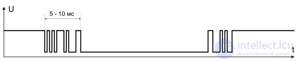
The transient process usually lasts a few milliseconds. Therefore, on each press the button produces many signal edges, and on each edge our program inverts the LED's state. That is, the LED shows an even or odd number of edges in the button's signal.
It's clear that the button signal must be processed in software to eliminate contact bounce. There is another problem - electromagnetic interference. If the button is connected with long wires, short pulses of electromagnetic interference may appear in the signal, leading to additional false triggers.
A reliable program must always process signals from buttons and mechanical sensors.
How to deal with contact bounce?
There are several ways to handle contact bounce. The one described below – is one of the most reliable. I'll describe another method in later lessons.
So. The solution is fairly obvious. We must not react to frequent signal switching. A button cannot be pressed for, say, 0.0001 sec. So that's bounce. We need to wait until the button's state has been stable for a certain amount of time, and only then make a decision. And not react to frequent signal switching.
Program to eliminate button contact bounce.
Let's write such a program. To get closer to practical programming, let's break the program into blocks and try to properly design the interface between them.
There are ready-made functions for processing signals from buttons. You call the function with the pin number as an argument, and it returns the pin's state, “cleaned” of bounce. But the debouncing operation takes a significant amount of time, no less than the duration of the transient process, typically 10 ms. And the program will wait for the function's result for that entire time. And there can be several buttons. Also, besides reading button states, the program needs to do other things, and not every process can be interrupted for a long time.
So let's try to process button states as a parallel process. This is our first step towards multitasking. For now, towards a conditional form of multitasking.
Let's separate the button signal processing into its own program block. Let's set the condition that this block must be called regularly with a period of, say, 2 ms. To communicate with other program modules, let's create global variables that define the button's state. This way, the button signal will constantly be processed in a parallel process, and any part of the program can find out the button's state by checking these variables.
The program consists of two main blocks inside the infinite loop loop():
What might we need as a result of processing the button. What variables to create. As a rule, only two flags are needed:
We introduce global variables. Global, because it's unknown in which part of the program we'll want to check the button's state.
boolean flagPress= false; // flag: button is in the pressed state
boolean flagClick= false; // flag: button was pressed (edge)
We call the button signal processing block with a period of 2 ms. To time how long the signal's state has been stable, we need a button-state counter and a constant that sets this time.
byte buttonCount= 0; // counter of button-state confirmations
#define TIME_BUTTON 12 // time the button state must be stable (* 2 ms)
The purpose of the program block's functions is that it produces the flags:
If this block is called regularly with a period of 2 ms, the flags will correspond to the button's current state. They can be used by other blocks of the program anywhere. This results in parallel task execution.
Here is the sketch for a program built on this principle.
/* Program sketch_6_2, lesson 6
* Inverts the LED's state on every button press */
#define LED_PIN 13 // the LED's pin number is 13
#define BUTTON_PIN 12 // the button's pin number is 12
// variables and constants for button signal processing
boolean flagPress= false; // flag: button is in the pressed state
boolean flagClick= false; // flag: button was pressed (edge)
byte buttonCount= 0; // counter of button-state confirmations
#define TIME_BUTTON 12 // time the button state must be stable (* 2 ms)
boolean ledState; // LED state variable
void setup() {
pinMode(LED_PIN, OUTPUT); // define pin 13 (LED) as an output
pinMode(BUTTON_PIN, INPUT_PULLUP); // define pin 12 (button) as an input
}
// infinite loop with a period of 2 ms
void loop() {
/* button signal processing block
* when the button is pressed, flagPress= true
* when the button is released, flagPress= false
* when the button is pressed, flagClick= true */
if ( flagPress == (! digitalRead(BUTTON_PIN)) ) {
// flag flagPress = the button's current state
// (inverted, since the button's active state is LOW)
// i.e. the button's state stayed the same
buttonCount= 0; // reset the button-state confirmation counter
}
else {
// flag flagPress does not = the button's current state
// the button's state changed
buttonCount++; // +1 to the button-state counter
if ( buttonCount >= TIME_BUTTON ) {
// the button's state hasn't changed during the set time
// the button's state has become stable
flagPress= ! flagPress; // invert the state flag
buttonCount= 0; // reset the button-state confirmation counter
if ( flagPress == true ) flagClick= true; // flag for the button's press edge
}
}
// LED control block
if ( flagClick == true ) {
// there was a button press
flagClick= false; // reset the button's press-edge flag
ledState= ! ledState; // invert the LED's state
digitalWrite(LED_PIN, ledState); // output the LED's state
}
delay(2); // delay of 2 ms
}
The following happens in the button-state processing block:
I don't think the LED control block needs any explanation.
The blocks are placed in an infinite loop with a period of 2 ms. This statement isn't entirely accurate, but let's not discuss that for now. The main thing is that the button signal processing block is called regularly, with a period of approximately 2 ms.
Upload the program to the Arduino controller, and check that it works reliably. No false triggers occur.
The constant TIME_BUTTON sets the button signal's stable-state time – 24 ms. I recommend choosing this time within the range of 20-30 ms.
To test the signal-processing algorithm, increase the constant TIME_BUTTON to 250 (time 500 ms). You'll see that on a quick press (less than 0.5 sec) the LED doesn't change its state. That is, the stable-state confirmation algorithm works correctly.
In this lesson we wrote a practical module for eliminating button bounce. You can use it in your own programs. In the next lesson I'll talk about classes in the Arduino programming language, and we'll create the button as an object.

Comments