
Lecture
At the time the board was released, the installation process for the Arduino IDE was fairly tedious and required installing GIT to clone the repository by hand. In Arduino IDE version 1.8.x, installation became simpler with the appearance of the "Boards Manager".
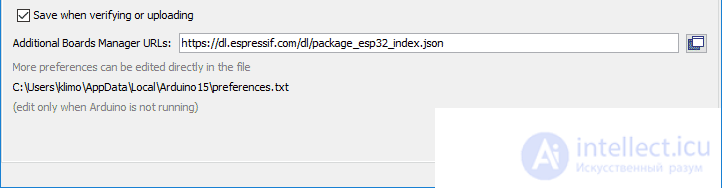
We open the File | Preferences menu in the Arduino IDE, and at the very bottom of the dialog box we find the Additional Boards Manager URLs block. In the text field we enter the address https://dl.espressif.com/dl/package_esp32_index.json. We save the settings by clicking the OK button.
If you have several different boards, the addresses can be separated with commas.
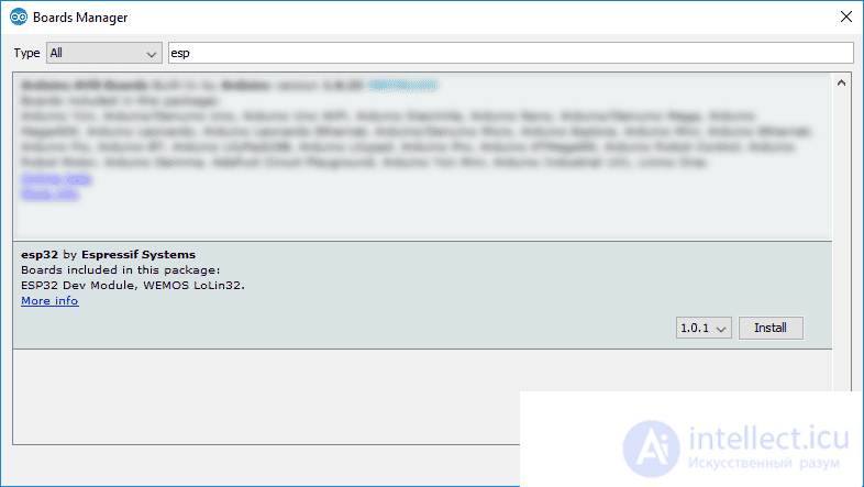
Next we open the Tools | Board | Board Manager... menu and in the dialog box select the ESP32 by Espressif Systems option (use the search for the word ESP32 to find it quickly).
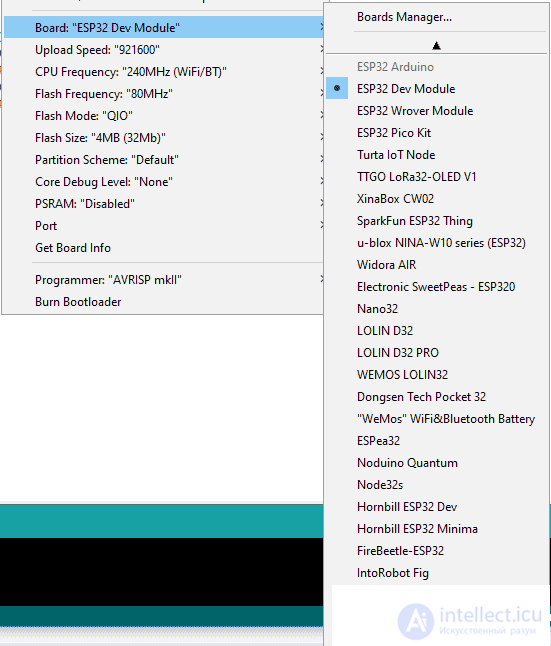
After these steps, a whole range of boards on the ESP32 platform will appear in the Arduino IDE, and you should select the specific model matching your actual board. For example, in my case it is the ESP32 Dev Module.
After that, as usual, we select the port and start writing sketches. But a problem may come up here - if you look at the port number in Device Manager (Windows), you may find that there is a problem device with no driver installed. You need to download the driver for your operating system from the CP210x USB to UART Bridge VCP Drivers page, for example the first link, Download for Windows 10 Universal (v10.1.6).
After this last step, the board is ready to work. You can open the built-in examples File | Examples | Examples for ESP32 Dev Module (or for another board on the ESP32 platform) and study the code.
If you use the standard sketch from File | Examples | 01.Basics | Blink, you will get an error. The reason is this - ESP32 has no LED_BUILTIN constant pointing to the built-in LED (which is rather strange). So you need to explicitly specify the board pin, as was done in older examples. Also, the built-in LED is not on pin 13, but on pin 2. Taking these features into account, the sketch for blinking the built-in LED will be as follows.
// Blinking the built-in LED on ESP32
const int LED = 2;

void setup() {
  pinMode(LED, OUTPUT);
}

void loop() {
  delay(1000);
  digitalWrite(LED, HIGH);
  delay(1000);
  digitalWrite(LED, LOW);
}
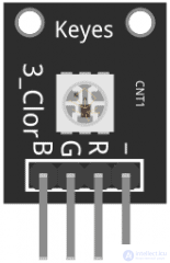
ESP32 has no analogWrite() function, so the standard approach does not work. Instead you can use other functions, covered in another article. For now, here is a simple example for turning on the primary colors without intermediate shades for an RGB LED module. We use pins 12, 13, 14 and GND.
void setup()
{
	pinMode(12, OUTPUT);
	pinMode(13, OUTPUT);
	pinMode(14, OUTPUT);
}

void loop()
{
	digitalWrite(12, HIGH);
	digitalWrite(13, HIGH);
	digitalWrite(14, HIGH);
	delay(2000);

	digitalWrite(12, LOW);
	digitalWrite(13, LOW);
	digitalWrite(14, LOW);
	delay(2000);

	digitalWrite(12, LOW);
	digitalWrite(13, HIGH);
	digitalWrite(14, LOW);
	delay(2000);

	digitalWrite(12, LOW);
	digitalWrite(13, LOW);
	digitalWrite(14, HIGH);
	delay(2000);
}
Another example of working with the RGB module
The board has a built-in temperature sensor that measures the chip temperature. The sensor cannot be used to measure the ambient air temperature, so in most cases it is useless. It is most likely to be useful with very resource-intensive tasks, when there is a risk of burning out the processor.
During testing it always showed 53.33 degrees for me. I don't even know whether it can be trusted at all.
#ifdef __cplusplus
extern "C" {
#endif

uint8_t temprature_sens_read();

#ifdef __cplusplus
}
#endif

uint8_t temprature_sens_read();

void setup() {
  Serial.begin(115200);
}

void loop() {
  Serial.print("Temperature: ");

  // Convert raw temperature in F to Celsius degrees
  Serial.print((temprature_sens_read() - 32) / 1.8);
  Serial.println(" C");
  delay(1000);
}
The board has a built-in Hall sensor that can detect magnets. Let’s write a sketch that turns on an LED when a magnet is detected. The current readings are also output to the Serial Monitor.
const int LED = 2;

void setup() {
  Serial.begin(115200);
  pinMode(LED, OUTPUT);
}

void loop() {
  int sensor = hallRead();  // read the Hall sensor value
  Serial.print("Sensor Reading:");
  Serial.println(sensor);

  digitalWrite(LED, (sensor < 0) ? HIGH : LOW); // turn on the LED when a magnet is detected
  delay(500);
}
The board has 2 analog outputs with a DAC (8 bit): pin 25 (DAC1) and pin 26 (DAC2). The analog output of the digital-to-analog converter allows generating 8-bit voltage levels.
#define DAC1 25

void setup() {
  Serial.begin(115200);
}

void loop() {
  int value = 128; // 255= 3.3V, 128=1.65V

  dacWrite(DAC1, value);
  delay(1000);
}
Run the sketch and check the voltage value on pin 25 with a multimeter. You can change the voltage level in the sketch.
SDK version, flash memory size, heap. The getSdkVersion() function has an equivalent in the low-level esp_get_idf_version() function, which returns the same answer.
void setup() {
  Serial.begin(115200);
  Serial.println("SDK");
  Serial.println(ESP.getSdkVersion());
  Serial.println("SDK via low-level function:");
  Serial.println(esp_get_idf_version());
}

void loop() {}
The response at the time this example was written.
SDK
v3.2.3-14-gd3e562907
SDK via low-level function:
v3.2.3-14-gd3e562907
The board has a ready-made restart() function for software restart. See the example in the API.
Let’s rewrite the example by adding a counter. It will count down once every second from 10 to 0.
int counter = 10;

void setup() {
  Serial.begin(115200);
}

void loop() {

  Serial.println(counter);

  if (counter == 0) {
    Serial.println("Reset..");
    ESP.restart();
  }

  counter--;
  delay(1000);
}
Arduino has the standard random() function for getting random numbers. ESP32 has its own additional esp_random() function, which returns a number from 0 to UINT32_MAX (the largest unsigned INT value). For the number to be truly random, the Wi-Fi or Bluetooth module must be running to take values from wireless signals.
Let’s write a sketch that uses all the available functions.
void setup() {
  Serial.begin(115200);
}

void loop() {
  Serial.println("-----------");
  Serial.println(esp_random());
  Serial.println(random(10)); // 0-9
  Serial.println(random(10, 20)); // 10-19

  delay(1000);
}
We convert a string to the BASE64 encoding scheme. There is a ready-made base64.h library for this.
#include

void setup() {
  Serial.begin(115200);
  String toEncode = "Hello Kitty";
  String encoded = base64::encode(toEncode);
  Serial.println(encoded);

}

void loop() {}
You can decode the message using online services, for example https://www.base64decode.org/.
Let’s look at an example of using a joystick.
Wiring (instead of 5V we use 3V). The sketch for the joystick remains unchanged, only the pin numbers change
KY-023 | ESP32
----------------
   GND | GND
   +5V | 3V3
   VRx | 2
   VRy | 4
    SW | 23

const int xPin = 2;
const int yPin = 4;
const int buttonPin = 23;
While for Arduino boards the joystick’s resting values are around 511-512, for ESP32 they are around 1445 (x), 1870 (y). The overall range of values is 0-4095.
In addition to the standard library for Arduino, there is a separate library for ESP32, available through the Library Manager under the keywords "DHT sensor library for ESPx by beegee".
General example.
#include "DHTesp.h"

DHTesp dht;

void setup()
{
  Serial.begin(115200);

  dht.setup(27);
}

void loop()
{
  float humidity = dht.getHumidity();

  Serial.print("Humidity: ");
  Serial.println(humidity);

  delay(10000);
}
There is an advanced version of the example for the DHT22 sensor. The sensor requires a delay of at least 2 seconds; we can find out a more precise delay value using the getMinimumSamplingPeriod() function
#include "DHTesp.h"

DHTesp dht;

void setup()
{
  Serial.begin(115200);

  dht.setup(27);

  Serial.print("Minimum Sampling Period: ");
  Serial.println(dht.getMinimumSamplingPeriod());
}

void loop()
{
  delay(dht.getMinimumSamplingPeriod());

  float temperature = dht.getTemperature();

  Serial.println("------------------");
  Serial.print("Temperature: ");
  Serial.println(temperature);

}
Normally, ESP32 runs on one of its two available cores. You can check this using the xPortGetCoreID() function.
void setup() {
  Serial.begin(115200);
  Serial.print("setup() function running on core: ");
  Serial.println(xPortGetCoreID());
}
void loop() {
  Serial.print("loop() function running on core: ");
  Serial.println(xPortGetCoreID());
  delay(3000);
}

// Result
// setup() function running on core: 1
// loop() function running on core: 1
The Arduino IDE supports FreeRTOS, and its API allows creating tasks that can run independently on either core.
Let’s create an example task using the xTaskCreatePinnedToCore() function, which takes seven (!) parameters.
// Example
xTaskCreatePinnedToCore(Task1code, "Task1", 10000, NULL, 1, NULL,  0);

Comments