
Lecture
Introduction.
There are a great many tutorials on the internet about programming the Arduino system. Most of them boil down to primitive programs that execute a sequence of actions using other people's functions.
It is immediately obvious that the programs are written in a highly unprofessional way.
Take, for example, my controller program for a refrigerator built around a Peltier element. How could it be made according to that principle? How could all the necessary actions be carried out using simple sequential operations? This program is written in PIC controller assembler. It performs a large number of parallel operations:
All these operations must be carried out cyclically, with different cycle periods. And nothing can be skipped or paused. Such a program cannot be implemented as a simple sequence of actions.
So, in my Arduino programming tutorials I intend to pay attention to the problems mentioned above, and I intend to teach practical programming. Programming Arduino controllers that work with real objects.
At the same time, I am aiming these tutorials at non-professional programmers, at people who want to learn to program controllers.
Despite the frightening-sounding terms – digital filtering, multitasking – this is much simpler than it seems. You simply need to rigorously handle every possible situation, not turn a blind eye to them.
Rather, these will be programming and electronics tutorials, since using microcontrollers without additional hardware makes no sense. They have to control something, after all.
In each tutorial I will strive to create a complete module that can be used in future projects. The ideal option is to create something like an operating system that uses drivers (functions) for all the external hardware. I managed to create such a system on PIC controllers for controlling complex packaging equipment. It includes an environment for running parallel tasks and drivers for working with stepper motors, sensors, buttons, a display, and so on. I hope it will work out on Arduino too.
General information about Arduino.
Arduino is the name of a hardware-and-software platform for creating simple electronic automation and robotics systems. The system has a fully open architecture and is aimed at non-professional users.
The software part of Arduino consists of an integrated development environment (IDE) that lets you write and compile programs, as well as upload them to the hardware.
The hardware part consists of electronic boards with a microcontroller, supporting components (a voltage regulator, a crystal oscillator, decoupling capacitors, etc.), a port for connecting to a personal computer, connectors for input/output signals, and so on.
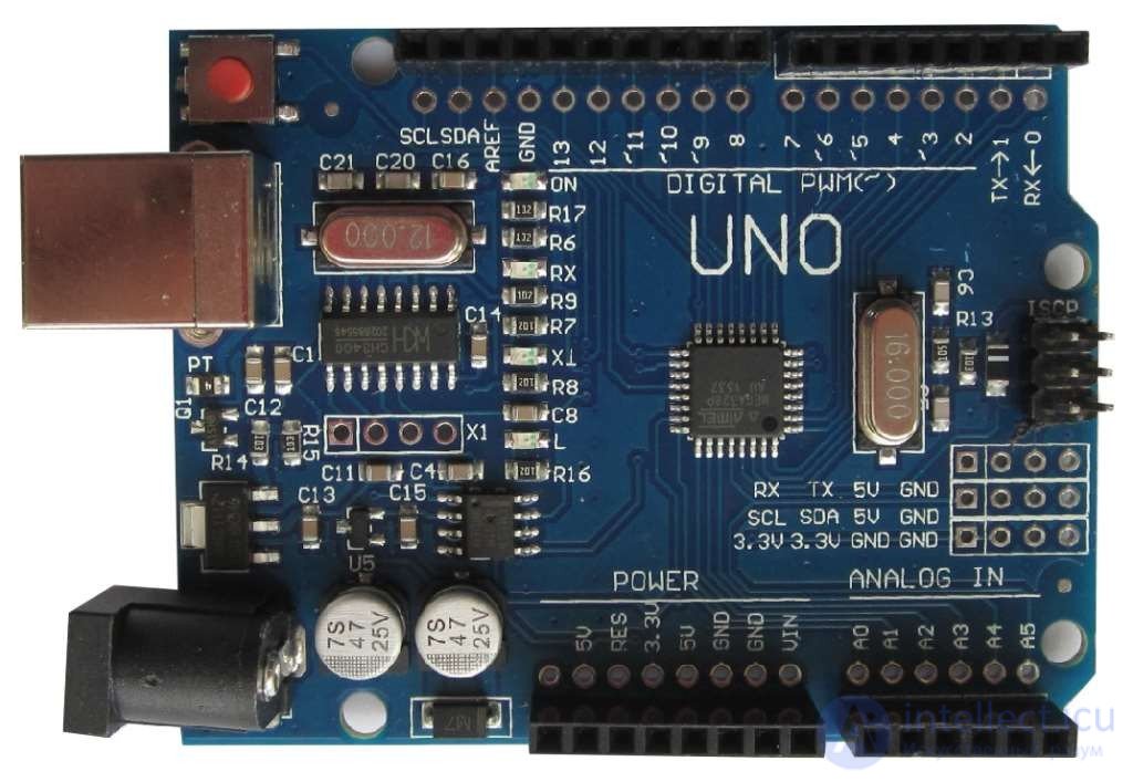
Thanks to the simplicity of designing devices, the Arduino system has become extremely widespread. On Yandex alone there are up to 150 thousand searches for”Arduino” per month. Despite the simplicity of project development, fairly complex systems can be built using Arduino, especially since the appearance of high-performance controller variants.
Arduino boards use Atmel AVR microcontrollers with a bootloader already flashed into them. The bootloader is used to load a program into the microcontroller from a personal computer without using hardware programmers.
The C/C++ language, with certain specifics, is used for programming Arduino.
There is a huge number of clones of the Arduino hardware. Most of them are complete analogues of official Arduino boards, and are often not inferior in quality.
General information about the controller.
The Arduino UNO R3 is built around the ATmega328 microcontroller. It has:
The board has all the components necessary to support the microcontroller's operation. It is enough to connect a USB cable to the computer and apply power. The microcontroller is mounted in a socket, which makes it easy to replace if it fails.
Specifications.
| Microcontroller type | ATmega328P |
| Microcontroller supply voltage | 5 V |
| Recommended board supply voltage | 7 – 12 V |
| Maximum permissible board supply voltage | 6 – 20 V |
| Digital I/O | 14 (6 of which support PWM) |
| PWM outputs | 6 |
| Analogue inputs | 6 |
| Permissible digital output current | 20 mA |
| Permissible current of the 3.3 V output | 50 mA |
| Flash memory size (FLASH) | 32 KB (of which 0.5 KB is used by the bootloader) |
| RAM size (SRAM) | 2 KB |
| Non-volatile memory size (EEPROM) | 1 KB |
| Clock frequency | 16 MHz |
| Board length | 68.6 mm |
| Board width | 53.4 mm |
| Weight | 25 g |
Programming.
The controller is programmed from the Arduino integrated development environment (IDE). Programming takes place under the control of a resident bootloader using the STK500 protocol. A hardware programmer is not required for this.
The microcontroller can also be programmed through the ICSP in-circuit programming connector, without using the bootloader. The source code of the bootloader program is freely available.
Difference from other Arduino controllers.
The Arduino UNO R3, unlike earlier versions, does not use an FTDI USB-UART bridge to connect to the computer. This function is performed by the ATmega16U2 microcontroller.
Power supply system.
The UNO board can be powered from the USB port or from an external source. The power source is selected automatically. A mains adapter or a battery can be used as the external power source. The adapter is connected through a 2.1 mm diameter connector (the center pin is positive). The battery is connected to the GND and Vin pins of the POWER connector.
The voltage of the external power source can be in the range of 6 – 20 V. However, it is recommended not to let the voltage drop below 7 V, because the device will operate unreliably. It is also undesirable to raise the supply voltage above 12 V, since the regulator may overheat and fail. That is, the recommended supply voltage range is 7 – 12 V.
The following pins can be used to connect power.
| Vin | Board power supply from an external source. Not connected to the 5 V supply from USB or to the outputs of the other regulators. This pin can be used to draw power for your own device if the board is powered from an adapter. |
| 5 V | Output of the board's voltage regulator. The voltage on it is 5 V regardless of the power source used. It is not recommended to power the board through this pin, since the regulator is bypassed, which could cause the microcontroller to fail. |
| 3 V 3 | 3.3 V voltage from the board's voltage regulator. The maximum permissible current draw from this pin is 50 mA. |
| GND | Common wire (ground). |
| IOREF | Provides information about the board's operating voltage on this pin. A shield can read this signal and switch to 5 V or 3.3 V power mode. |
Memory.
The microcontroller has three types of memory:
Inputs and outputs.
Each of the 14 digital pins can be used as an output or an input. The voltage level on the pins is 5 V. It is recommended to limit the sourcing and sinking current of each pin to 20 mA. The maximum permissible value of this parameter is 40 mA. Each pin has an internal pull-up resistor with a resistance of 20-50 kΩ. The resistor can be disabled in software.
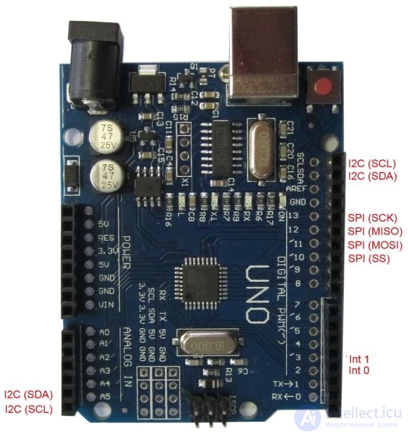
Some pins can perform additional functions.
Serial interface: pins 0 (Rx) and 1 (Tx). Used for receiving (Rx) and transmitting (Tx) serial data at TTL logic levels. These pins are connected to the corresponding data pins of the ATmega16U2 chip, which is used as a USB-UART bridge.
External interrupts: pins 2 and 3. These pins can be used as external interrupt inputs. They can be configured in software to trigger an interrupt on a low level, a rising or falling edge, or a change in signal level.
PWM: pins 3, 5, 6, 9, 10, 11. Can operate in PWM mode with 8-bit resolution.
SPI serial interface: pins 10(SS), 11(MOSI), 12(MISO), 13(SCK).
LED: pin 13. An LED connected to pin 13. It lights up when the signal on the pin is high.
TWI interface: pin A4 or SDA and A5 or SCL. A TWI communication interface.
The Arduino UNO board has 6 analogue inputs, labeled A0-A5. The resolution of the analogue-to-digital conversion is 10 bits. By default, the input voltage is measured relative to ground over the range of 0-5 V, but this can be changed using the AREF pin and software settings.
Two more pins on the board have the following functions:
AREF. The reference voltage for the microcontroller's ADC.
RESET. A low level on this pin causes the microcontroller to reset.
Communication interfaces.
The Arduino UNO module has the means to communicate with a computer, with another UNO board, or with other microcontrollers. For this purpose, the board has a UART interface with TTL logic levels (5 V), connected to pins 0 (RX) and 1(TX). The ATmega16U2 chip on the board links the UART interface to the computer's USB port. When connected to the computer's port, a virtual COM port appears, through which the computer's programs communicate with the Arduino. The ATmega16U2 firmware uses standard USB-COM drivers, and installing additional drivers is not required. For the Windows operating system, the corresponding .inf file is needed. The Arduino integrated development environment (IDE) includes a Serial Monitor that allows simple text data to be sent to and received from the board. The board has RX and TX LEDs that indicate the state of the corresponding signals for communication over USB (but not for the serial interface on pins 0 and 1).
The ATmega328 microcontroller also supports the I2C (TWI) and SPI communication interfaces.
Automatic (software) reset.
So that it is not necessary to press the reset button every time before uploading a program, the UNO board implements a hardware reset function triggered from the connected computer. One of the data flow control signals (DTR) of the ATmega16U2 chip is connected to the reset pin of the ATmega328 microcontroller through a 0.1 µF capacitor. When the DTR signal goes low, a reset pulse is generated for the microcontroller. This solution allows the program to be uploaded with a single button press from the Arduino integrated development environment (IDE).
However, this function can have negative consequences. When the UNO board is connected to a computer running Mac OS X or Linux, the microcontroller will reset every time a program connects to the board. For about half a second, the bootloader will be running on the UNO board. Although the bootloader program ignores extraneous data, it may pick up a few bytes from a packet right after the connection is established. If a program on the Arduino board is designed to receive some data on first startup, the data should be sent with a delay of about 1 second after the connection is made.
On the UNO module there is a trace that can be cut to disable the automatic reset function. The trace is labeled”RESET-EN”. Automatic reset can also be disabled by connecting a 110 Ω resistor between the 5 V supply line and the RESET pin.
USB port overload protection.
On the Arduino UNO board, the power line from the USB interface is protected by a resettable fuse. If the current exceeds 500 mA, the fuse breaks the circuit until the short circuit is cleared.
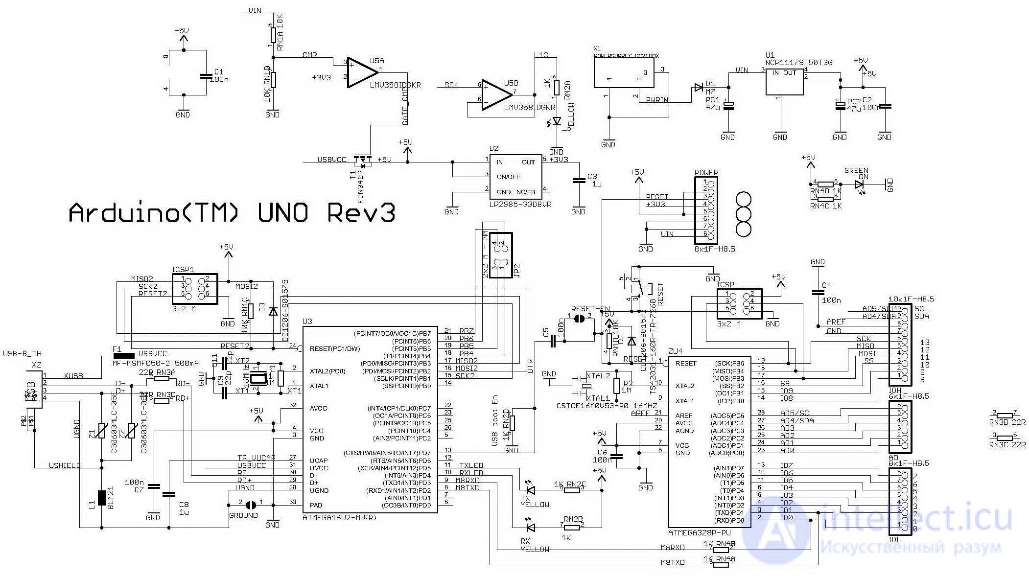
Circuit diagram of the Arduino UNO controller.

Comments