
Lecture
The ESP32 board has 15 analogue inputs with a 12-bit ADC: 2, 4, 12–15, 25–27, 32–36 and 39. This lets you represent an analogue voltage digitally with a 12-bit resolution.
To take a reading, it is enough to call the analogRead(GPIO) function, specifying the pin you need.
In doing so, we read a voltage level from 0V to 3.3V, which is mapped to a range from 0 to 4095.
As an example, let's connect a potentiometer to pin 34 and read the values through the Serial Monitor.
// Connect the potentiometer to pin GPIO 34 (Analog ADC1_CH6)
const int potPin = 34;

// reading
int potValue = 0;

void setup() {
  Serial.begin(115200);
  delay(1000);
}

void loop() {
  // read the value
  potValue = analogRead(potPin);
  Serial.println(potValue);
  delay(500);
}
Keep in mind that the readings are not strictly linear. For example, a voltage from 3.2 to 3.3 will still output a value of 4095, and similarly, a voltage from 0 to 0.1 will read as 0.
When using WiFi, use pins 32, 33, 34, 35, 36, 39 for analogue inputs. The others may cause problems.
There are non-standard functions of its own for working with analogue inputs.
Web server. Controlling digital pins
Web server. Reading values from analogue pins
Socket server. Communicating via Putty
You can read about connecting to a WiFi network in a separate article.
The WiFi.h library includes the WiFiServer class, which lets you use the board as a server. To initialize it, you need to call the class constructor and specify the port number, for example, 80.
Among the Examples/WiFi examples there is the SimpleWiFiServer example for creating a web server that can turn an LED on and off. In the example, the LED is connected to pin 5. In the sketch, you need to specify the name and password of your WiFi network. After starting it up, you will get your IP address through the Serial Monitor. Open a browser on your computer or phone and you will see a page with two links. You can also control the LED via the address bar: http://yourAddress/H turns the LED on, and http://yourAddress/L turns it off.
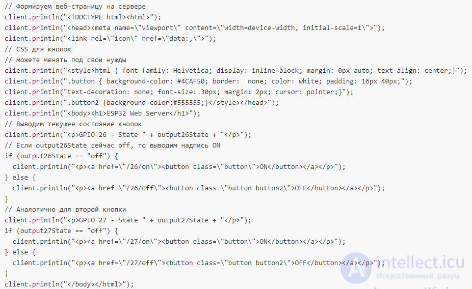
Let's create an extended example of a web server.
The ESP32 board can work as a web server. Let's connect two LEDs to the board on pins 26 and 27, or choose other ones.
After uploading the sketch to the board, we will find out its web address, which we can connect to through a browser on a home computer or phone using the local WiFi network. At that address there will be a page with two buttons that let you turn the LEDs on or off.
// Load the Wi-Fi library
#include
// Replace with your own SSID and password
const char* ssid = "your_ssid";
const char* password = "your_pass";
// Port number for the server
WiFiServer server(80);
// HTTP request
String header;
// current button state
String output26State = "off";
String output27State = "off";
// Pin numbers
const int output26 = 26;
const int output27 = 27;
void setup() {
Serial.begin(115200);
// Configure the board pins
pinMode(output26, OUTPUT);
pinMode(output27, OUTPUT);
// Set the pins to LOW
digitalWrite(output26, LOW);
digitalWrite(output27, LOW);
// Connect to Wi-Fi
Serial.print("Connecting to ");
Serial.println(ssid);
WiFi.begin(ssid, password);
while (WiFi.status() != WL_CONNECTED) {
delay(500);
Serial.print(".");
}
// Print the local IP address and start the server
Serial.println("");
Serial.println("WiFi connected.");
Serial.println("IP address: ");
Serial.println(WiFi.localIP());
server.begin();
}
void loop() {
WiFiClient client = server.available(); // listen for incoming clients
if (client) { // If a new client connects,
Serial.println("New Client."); // print a message
String currentLine = "";
while (client.connected()) { // loop while the client is connected
if (client.available()) { // if data is coming from the client,
char c = client.read(); // read a byte, then
Serial.write(c); // print it to the screen
header += c;
if (c == '\n') { // if the byte is a newline
// if the line is blank, we have received two newline characters in a row
// that means this is the end of the HTTP request, so we build the server's response:
if (currentLine.length() == 0) {
// HTTP headers start with a response code (e.g. HTTP/1.1 200 OK)
// and content-type, then a blank line:
client.println("HTTP/1.1 200 OK");
client.println("Content-type:text/html");
client.println("Connection: close");
client.println();
// Turn the LEDs on or off
if (header.indexOf("GET /26/on") >= 0) {
Serial.println("GPIO 26 on");
output26State = "on";
digitalWrite(output26, HIGH);
} else if (header.indexOf("GET /26/off") >= 0) {
Serial.println("GPIO 26 off");
output26State = "off";
digitalWrite(output26, LOW);
} else if (header.indexOf("GET /27/on") >= 0) {
Serial.println("GPIO 27 on");
output27State = "on";
digitalWrite(output27, HIGH);
} else if (header.indexOf("GET /27/off") >= 0) {
Serial.println("GPIO 27 off");
output27State = "off";
digitalWrite(output27, LOW);
}
 // The HTTP response ends with a blank line
client.println();
break;
} else { // if we received a new line, clear currentLine
currentLine = "";
}
} else if (c != '\r') { // If we received anything other than a carriage return,
currentLine += c; // add it to the end of currentLine
}
}
}
// Clear the variable
header = "";
// Close the connection
client.stop();
Serial.println("Client disconnected.");
Serial.println("");
}
}
// The HTTP response ends with a blank line
client.println();
break;
} else { // if we received a new line, clear currentLine
currentLine = "";
}
} else if (c != '\r') { // If we received anything other than a carriage return,
currentLine += c; // add it to the end of currentLine
}
}
}
// Clear the variable
header = "";
// Close the connection
client.stop();
Serial.println("Client disconnected.");
Serial.println("");
}
}
Open the Serial Monitor, find out the server's address, and connect to it from a computer or phone. A page with buttons will open; press them to control the LEDs.
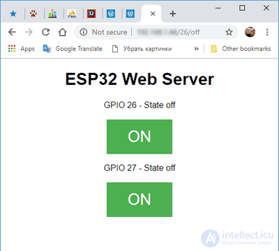
While working with the server, watch the messages in the Serial Monitor, which shows information about new clients connecting.
We use GET requests for communication, so when you press the buttons, the address in the browser will change to .../26/on.
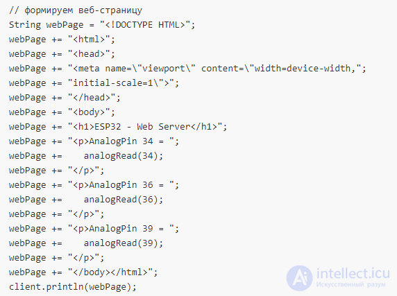
We can also take readings from analogue pins; in our example these will be pins 34, 36, 39.
// Load the Wi-Fi library
#include
// Replace with your own Wi-Fi access point SSID and password
const char* ssid = "your_ssid";
const char* password = "your_pass";
// Port number for the server
WiFiServer server(80);
// set up a buffer and a counter for the buffer
char lineBuf[80];
int charCount = 0;
void setup() {
Serial.begin(115200);
// pause to allow time to open the Serial Monitor
delay(5000);
// initialize the analogue pins
pinMode(34, INPUT);
pinMode(36, INPUT);
pinMode(39, INPUT);
// Connect to Wi-Fi
Serial.println();
Serial.print("Connecting to ");
Serial.println(ssid);
WiFi.begin(ssid, password);
while (WiFi.status() != WL_CONNECTED) {
delay(500);
Serial.print(".");
}
// Print the local IP address and start the server
Serial.println("");
Serial.println("Wi-Fi connected");
Serial.println("IP-address: ");
Serial.println(WiFi.localIP());
// start the server
server.begin();
}
void loop() {
WiFiClient client = server.available(); // listen for incoming clients
if (client) {
Serial.println("New client");
memset(lineBuf, 0, sizeof(lineBuf));
charCount = 0;
// The HTTP request ends with a blank line
boolean currentLineIsBlank = true;
while (client.connected()) {
client.println("HTTP/1.1 200 OK");
client.println("Content-Type: text/html");
client.println("Connection: close");
client.println();
// build the web page
 break;
}
// Give the web browser time to receive the data
delay(1);
// Close the connection
client.stop();
Serial.println("client disconnected");
}
}
break;
}
// Give the web browser time to receive the data
delay(1);
// Close the connection
client.stop();
Serial.println("client disconnected");
}
}
Open the Serial Monitor, find the server's address, connect to the page, and get the readings from the analogue pins.
Using the ESP32 as a web server is not always convenient or justified. We can communicate with the microcontroller through sockets.
The beginning of the code is exactly the same - we specify our SSID and password to log in to the WiFi network, then initialize a WiFiServer object and try to join the network. If successful, we will get the board's IP address in the Serial Monitor. You should remember it.
#include

// Replace with your own SSID and password
const char* ssid     = "your_ssid";
const char* password = "your_pass";

// Port number for the server
WiFiServer wifiServer(80);

void setup() {
  Serial.begin(115200);

  delay(1000);

  WiFi.begin(ssid, password);

  while (WiFi.status() != WL_CONNECTED) {
    delay(1000);
    Serial.println("Connecting to WiFi..");
  }

  Serial.println("Connected to the WiFi network");
  Serial.println(WiFi.localIP());

  wifiServer.begin();
}

void loop() {
  WiFiClient client = wifiServer.available();

  if (client) {
    while (client.connected()) {
      while (client.available() > 0) {
        char c = client.read();
        Serial.write(c);
      }
      delay(10);
    }

    client.stop();
    Serial.println("Client disconnected");
  }
}
After you run the code on the ESP32, you can connect to the board using the Putty application on your computer.
Download the latest version of Putty; I choose the zip version without an installer.
Launch the application, enter the IP address that you should see in the Serial Monitor, and set the connection port number to 80.
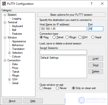
After that, a black terminal window will open, in which you can type text. A command must be finished by pressing Enter.
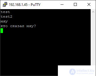
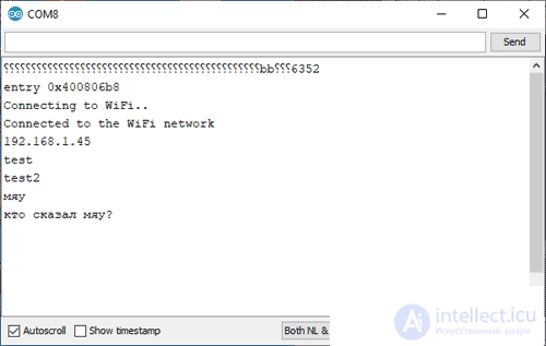
In the Serial Monitor you will see your commands.

Comments