
Lecture

Home page for the ESP32 board for Arduino on GitHub - github.com/espressif/arduino-esp32
The hardware of the IoT platform is built on the ESP-WROOM-32 module with the ESP32-D0WDQ6 system on a chip made by Espressif.
The ESP32-D0WDQ6 chip — is manufactured using SoC (System-on-a-Chip) technology.
The ESP32-WROOM — is a module containing the ESP32-D0WDQ6 chip, 4 MB of flash memory and all the necessary supporting circuitry, hidden under a metal shield. Next to the shield is a miniature antenna formed by a trace on the top layer of the PCB. The metal shield screens the module's components, thereby improving its electromagnetic properties.
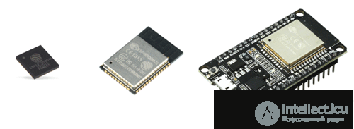
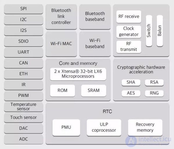
The die contains a dual-core 32-bit Tensilica Xtensa LX6 processor, 520 KB of SRAM and 448 KB of flash memory, plus 4 MB of external flash memory. The clock frequency can be set up to 240 MHz depending on the power mode.
It also has a built-in temperature sensor, a Hall sensor, an infrared receive/transmit controller, a touch-button controller, Bluetooth (BLE v4.2 BR/EDR), and Wi-Fi (Wi-Fi 802.11 b/g/n standards (2.4 GHz)).
A USB-to-UART converter based on the CP2102 chip provides the connection between the ESP32-WROOM module and the computer's USB port. When connected to a PC — the ESP32 DevKit board is recognised as a virtual COM port.
The micro-USB connector is used for flashing and powering the ESP32 DevKit board from a computer.
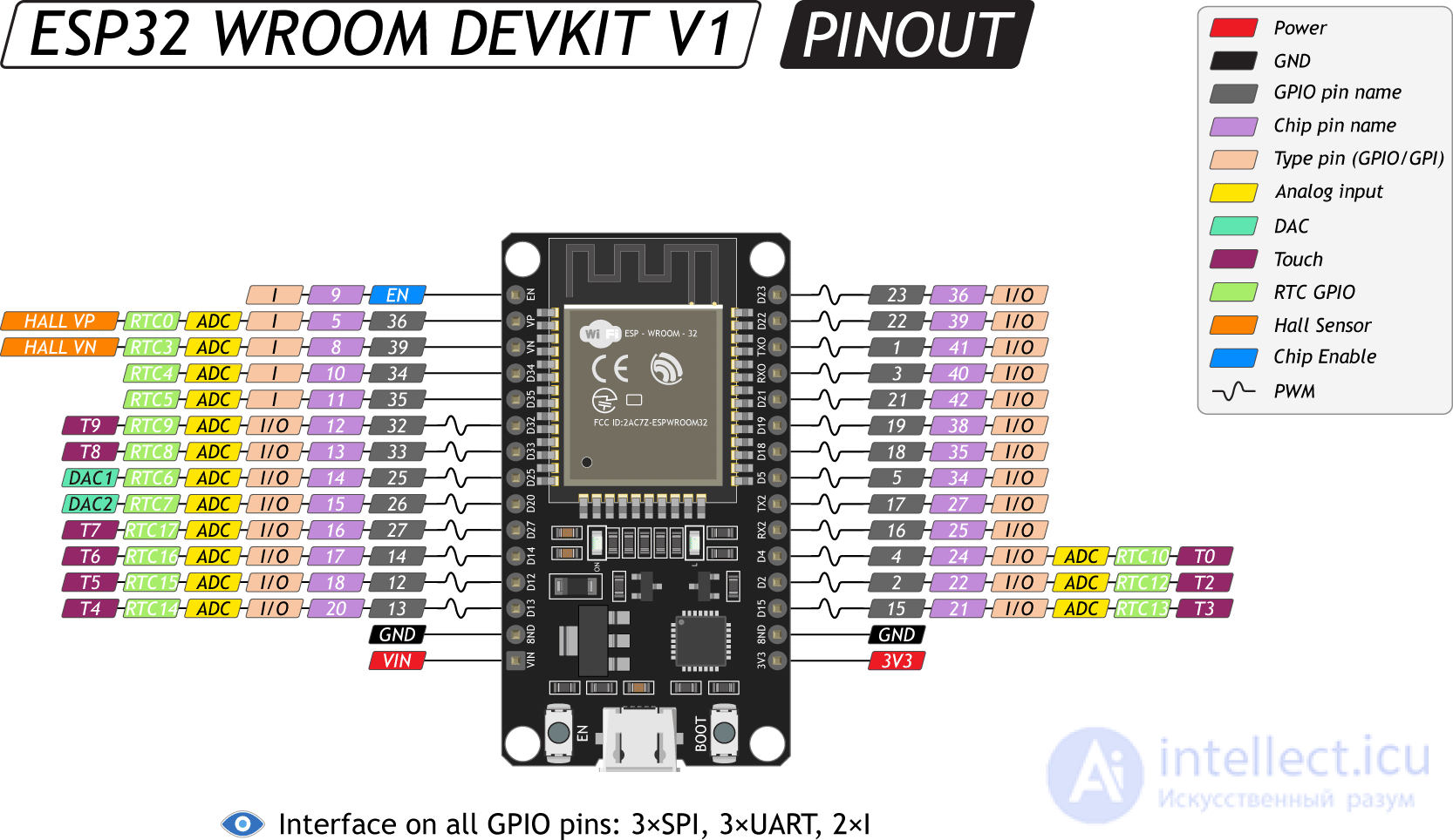
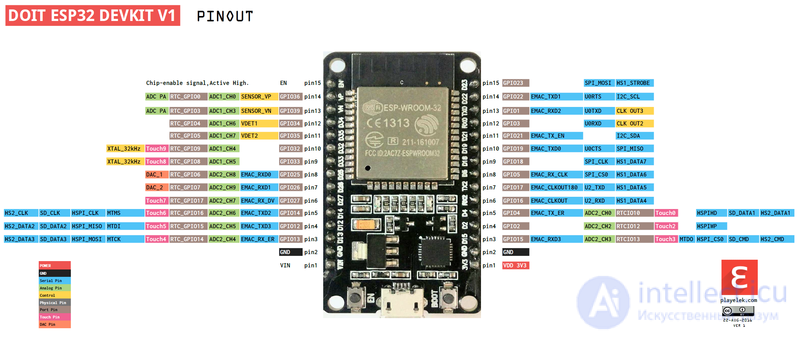
On both sides of the board there are pin headers with 15 pins each, at a 2.54 mm pitch (a 30-pin version also exists).
25 general-purpose pins are available. All pins support interrupts. Maximum current per pin: 12 mA.
The I/O pins can be configured to provide hardware interfaces:
For experiments, use pins 2, 4, 12, 13, 14, 18, 19, 21, 22, 23, 25, 26, 27.
Summary table of pins for use in projects
Summary table of pins for use in projects
| GPIO | Input | Output | Notes |
| 0 | pulled up | OK | outputs PWM signal at boot |
| 1 | TX pin | OK | debug output at boot |
| 2 | OK | OK | connected to on-board LED |
| 3 | OK | RX pin | HIGH at boot |
| 4 | OK | OK | |
| 5 | OK | OK | outputs PWM signal at boot |
| 6 | x | x | connected to the integrated SPI flash |
| 7 | x | x | connected to the integrated SPI flash |
| 8 | x | x | connected to the integrated SPI flash |
| 9 | x | x | connected to the integrated SPI flash |
| 10 | x | x | connected to the integrated SPI flash |
| 11 | x | x | connected to the integrated SPI flash |
| 12 | OK | OK | boot fail if pulled high |
| 13 | OK | OK | |
| 14 | OK | OK | outputs PWM signal at boot |
| 15 | OK | OK | outputs PWM signal at boot |
| 16 | OK | OK | |
| 17 | OK | OK | |
| 18 | OK | OK | |
| 19 | OK | OK | |
| 21 | OK | OK | |
| 22 | OK | OK | |
| 23 | OK | OK | |
| 25 | OK | OK | |
| 26 | OK | OK | |
| 27 | OK | OK | |
| 32 | OK | OK | |
| 33 | OK | OK | |
| 34 | OK | input only | |
| 35 | OK | input only | |
| 36 | OK | input only | |
| 39 | OK | input only |
The development board has two push-buttons. The EN button is used to manually reset the board - the equivalent of the RESET button on a regular computer.
The Boot button is used to manually enter the module's flashing mode. The procedure is as follows: hold down the BOOT button; press and release the EN button; release the BOOT button.
The board also has a power LED and an indicator LED connected to digital pin 2 (instead of pin 13 as on standard Arduino boards).
The AMS1117-3.3 linear step-down voltage regulator powers the microcontroller. Output voltage is 3.3 volts with a maximum current of 1 A.
Power is supplied through the micro-USB connector or the Vin pin. The source is detected automatically.
When powering via USB, use a 5V charger together with a Micro USB cable. When powering via Vin, an input voltage of 5 to 14 V is recommended. The board's power converter will regulate the input voltage down to the required 3.3 V.
As with Arduino boards, ESP32 boards also come from different manufacturers with different numbers of pins and different supporting circuitry. Variants of specific boards also appear. For example, the ESP32 DEVKIT DOIT board comes with 30 and 36 pins.
The ESP32 SoC offers substantially improved specifications compared to its predecessor, but it also costs more. So it is up to everyone to decide which one to use.
Let's create a project using PlatformIO:
mkdir esp32-intro
cd esp32-intro
pio init -b esp32doit-devkit-v1 --ide vscode
In the src directory, let's create a file called Main.cpp with the following contents (yes, it's the classic blinker):
#include <Esp.h>

void setup() {
    pinMode(LED_BUILTIN, OUTPUT);
}

void loop() {
    digitalWrite(LED_BUILTIN, HIGH);
    delay(100);
    digitalWrite(LED_BUILTIN, LOW);
    delay(900);
}
And in the platformio.ini file, in the [env:esp32doit-devkit-v1] section, let's add a parameter specifying the upload speed:
upload_speed = 921600
In this case it makes sense, since the ESP32 SoC has high performance, and increasing the channel speed improves the upload speed. Although for me it turned out to be variable: from six to ten seconds.
Let's build our application:
pio run
And upload it:
pio run -t upload
Actually, it isn't necessary to give two separate commands. Calling
pio run -t uploadon its own will rebuild the application if needed. I give two commands purely so I can see how long it takes to upload the application to the board.
The upload process prints a fairly detailed log.
[Fri Sep 29 11:52:53 2017] Processing esp32doit-devkit-v1 (platform: espressif32; upload_speed: 921600; board: esp32doit-devkit-v1; framework: arduino)
-------------------------------------------------------------------------------------------------------------------------------------------------------
Verbose mode can be enabled via `-v, --verbose` option
Collected 15 compatible libraries
Looking for dependencies...
No dependencies
Looking for upload port...
Auto-detected: /dev/ttyUSB0
Uploading .pioenvs/esp32doit-devkit-v1/firmware.bin
esptool.py v2.1-beta1
Connecting........_
Chip is ESP32D0WDQ6 (revision 1)
Uploading stub...
Running stub...
Stub running...
Changing baud rate to 921600
Changed.
Configuring flash size...
Auto-detected Flash size: 4MB
Flash params set to 0x022f
Compressed 10464 bytes to 7012...
Wrote 10464 bytes (7012 compressed) at 0x00001000 in 0.1 seconds (effective 1044.7 kbit/s)...
Hash of data verified.
Compressed 3072 bytes to 122...
Wrote 3072 bytes (122 compressed) at 0x00008000 in 0.0 seconds (effective 8280.8 kbit/s)...
Hash of data verified.
Compressed 8192 bytes to 47...
Wrote 8192 bytes (47 compressed) at 0x0000e000 in 0.0 seconds (effective 35367.7 kbit/s)...
Hash of data verified.
Compressed 356880 bytes to 177296...
Wrote 356880 bytes (177296 compressed) at 0x00010000 in 3.2 seconds (effective 891.6 kbit/s)...
Hash of data verified.

Leaving...
Hard resetting...
==== [SUCCESS] Took 8.46 seconds ====
The log reveals an interesting innovation in the bootloader: the firmware is transferred in compressed form, which considerably speeds up the data transfer process and, as a result, the overall upload speed.

Comments