
Lecture
A half adder is a combinational logic circuit with two inputs and two outputs (a two-bit adder, a binary adder).
A half adder (or half-adder) is a combinational logic circuit that performs the addition of two single-digit binary numbers. It has two inputs representing the addends, and two outputs: one for the sum and one for the carry.
A half adder computes the sum A+B, where A and B are digits (bits), usually of a binary number, and the result is two bits, S and C, where S is the sum bit modulo 2 and C is the carry bit.
Adders and half adders that do not operate in binary logic also exist.
It differs from a full adder in that it has no carry input from the previous digit. Building a full adder requires an additional carry input from the previous digit, so a full adder has 3 inputs.
A binary full adder is built from two half adders and a 2-input OR gate, which is precisely why the circuit under discussion is called a half adder.
Half adders are used to build full adders.

Standard symbol for a binary half adder per DIN 40900.

A half adder implemented using EXCLUSIVE OR and AND gates.

A half adder implemented using OR gates with inverted inputs, and an AND gate.
A binary half adder can be defined in three ways:
Since formulas and circuits can be transformed according to the laws of logic algebra, a single truth table of a binary half adder can correspond to a multitude of different formulas and circuits. For this reason, the tabular method of defining a binary half adder is the primary one.
A binary half adder implements two binary (two-operand) binary logic functions: sum modulo two, otherwise called the EXCLUSIVE OR (XOR) function, which produces the sum bit S, and the AND function, which produces the carry bit C.
S
| 1 | 1 | 0 |
|---|---|---|
| 0 | 0 | 1 |
| 0 | 1 |
C
| 1 | 0 | 1 |
|---|---|---|
| 0 | 0 | 0 |
| 0 | 1 |
or in another form:
| x0=A | 1 | 0 | 1 | 0 | ||
|---|---|---|---|---|---|---|
| x1=B | 1 | 1 | 0 | 0 | Function name | Function number |
| S | 0 | 1 | 1 | 0 | Sum bit modulo 2 | F2,6 |
| C | 1 | 0 | 0 | 0 | Carry bit | F2,8 |
A nonzero carry occurs in 1 case out of 4.
Canonical disjunctive normal form of the sum modulo 2:

Canonical disjunctive normal form of the carry bit:

The demonstration Stibitz half adder, the “Model K Adder”, is used for educational purposes and consists of: two galvanic cells connected in series, 1.5 volts each, with a combined voltage of 3 volts; two buttons for entering the two argument bits A and B; two electromagnetic relays performing the binary logic function of addition modulo 2 and the binary logic function of the carry bit in binary addition; and two incandescent lamps rated at 3 volts for indicating the sum bit modulo 2 (S) and the carry bit (C)
Since there are two ternary number systems — unbalanced, in which the carry digit never exceeds “1”, and balanced (Fibonacci), in which the carry digit can take all three trit states — and there are at least three physical implementations of ternary systems — three-level single-wire, two-level two-wire (BCT), and two-level three-bit one-hot — there can accordingly be a great many ternary half adders.
A ternary half adder in the unbalanced ternary number system is a combination of two binary ternary logic functions — “addition modulo 3” and “carry digit in ternary addition”.
S
| 2 | 2 | 0 | 1 |
|---|---|---|---|
| 1 | 1 | 2 | 0 |
| 0 | 0 | 1 | 2 |
| 0 | 1 | 2 |
C
| 2 | 0 | 1 | 1 |
|---|---|---|---|
| 1 | 0 | 0 | 1 |
| 0 | 0 | 0 | 0 |
| 0 | 1 | 2 |
or in another form:
| x1=x | 2 | 2 | 2 | 1 | 1 | 1 | 0 | 0 | 0 | ||
|---|---|---|---|---|---|---|---|---|---|---|---|
| x0=y | 2 | 1 | 0 | 2 | 1 | 0 | 2 | 1 | 0 | Function name | Function number |
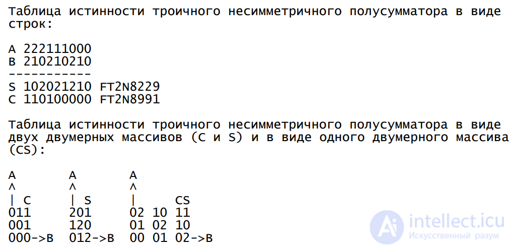
| S | 1 | 0 | 2 | 0 | 2 | 1 | 2 | 1 | 0 | Sum trit modulo 3 | 1020212103=822910 |
| C | 1 | 1 | 0 | 1 | 0 | 0 | 0 | 0 | 0 | Carry trit | 1101000003=899110 |
A ternary half adder in the balanced ternary number system is also a half subtractor, and represents a combination of two binary ternary logic functions — the “low-order digit (trit) of the sum-difference” and the “high-order digit (trit) of the sum-difference (the carry digit in addition-subtraction in the balanced ternary number system)”.
S
| +1 | 0 | +1 | -1 |
|---|---|---|---|
| 0 | -1 | 0 | +1 |
| -1 | +1 | -1 | 0 |
| -1 | 0 | +1 |
C
| +1 | 0 | 0 | +1 |
|---|---|---|---|
| 0 | 0 | 0 | 0 |
| -1 | -1 | 0 | 0 |
| -1 | 0 | +1 |
or in another form:
| x1=x | 1 | 1 | 1 | 0 | 0 | 0 | 7 | 7 | 7 | ||
|---|---|---|---|---|---|---|---|---|---|---|---|
| x0=y | 1 | 0 | 7 | 1 | 0 | 7 | 1 | 0 | 7 | Function name | Function number |
| S | 7 | 1 | 0 | 1 | 0 | 7 | 0 | 7 | 1 | Low-order sum trit | F710107071=F-4160 |
| C | 1 | 0 | 0 | 0 | 0 | 0 | 0 | 0 | 7 | High-order sum trit (carry trit) | F100000007=F6560 |
The digit “7” here denotes “-1”
A nonzero carry occurs in 2 cases out of 9.
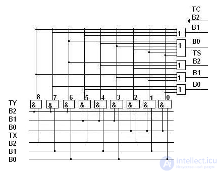
Ternary half adder.
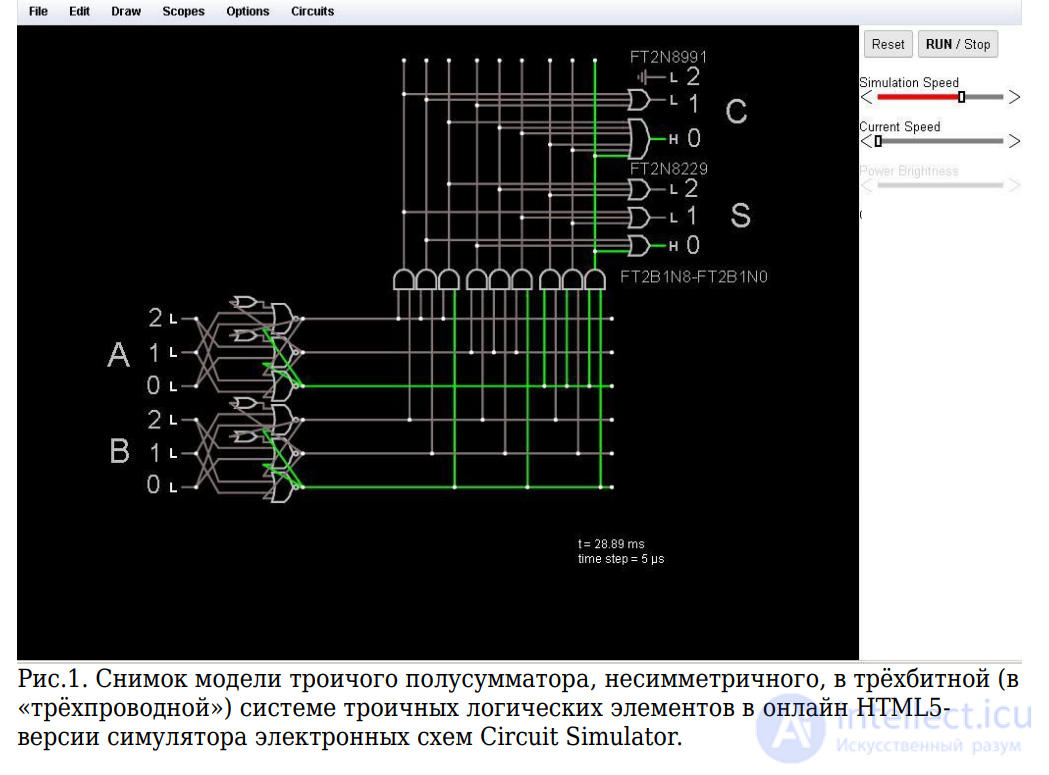
The figure shows a circuit diagram of an unbalanced ternary half adder in the three-bit one-hot system of ternary logic elements, described in.
A mirror-symmetric single-digit ternary half adder is modeled below.
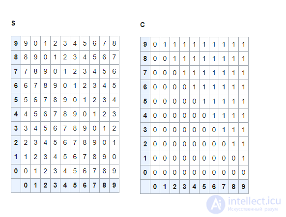
It consists of two 10×10 tables. The first table gives the sums modulo 10, the second table gives the carry units in binary (two-operand) decimal addition.
Single-digit two-operand (two-argument) decimal addition is one of the  binary (two-argument, two-operand, two-input) decimal logic functions with a binary (two-digit) result, which, besides its own number, also has its own name in words: "single-digit decimal half adder".
In the theory of functional systems and in decimal logic, a decimal function is a function of the type  , where D={0,1,2,3,4,5,6,7,8,9} is the decimal set, and n
 is a non-negative integer called the arity of the function.
In total there are  simplest binary decimal logic functions with a binary (two-digit) result (2 decits -> 2 decits), where m is the number of arguments of the function (the input "-arity") and n is the number of outputs the function produces (the output "-arity"), a number greater than all of Dirac's large numbers combined, and, on top of that, greater than Shannon's number (the estimated minimum number of non-repeating chess games, computed in 1950 by the American mathematician Claude Shannon, is approximately 10120
 ).
).
Single-digit two-operand (two-argument) decimal addition can also be represented as a combination (union of two) binary (two-argument, two-operand, two-input) decimal logic functions with a unary (single-digit) result, which, besides their own numbers, also have their own names in words: "single-digit decimal binary addition modulo 10" and "carry unit into the next digit in single-digit decimal binary addition".
In total there are 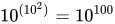 simplest binary decimal logic functions with a unary (single-digit) result (2 decits -> 1 decit).
The number of the function "single-digit decimal binary addition modulo 10" contains all values of the function as the argument values range from 0 to 9, and is obtained relatively simply from the decimal half-adder table: 8765432109 7654321098 6543210987 5432109876 4321098765 3210987654 2109876543 1098765432 0987654321 9876543210 (the spaces separate groups of 10 digits in the function number).
The number of the function "carry unit into the next digit in single-digit decimal binary addition" contains all values of the function as the argument values range from 0 to 9, and is likewise obtained relatively simply from the decimal half-adder table: 1111111110 1111111100 1111111000 1111110000 1111100000 1111000000 1110000000 1100000000 1000000000 0000000000 (the spaces separate groups of 10 digits in the function number).
Since the carry digit never takes a value greater than 1, the carry digit in a single-digit decimal half adder is a simpler decimal function with a unary (single-digit) binary result (2 decits -> 1 bit).
'Half Adder Decimal Single-Digit
CLS
DATA 0,1,2,3,4,5,6,7,8,9
DATA 1,2,3,4,5,6,7,8,9,0
DATA 2,3,4,5,6,7,8,9,0,1
DATA 3,4,5,6,7,8,9,0,1,2
DATA 4,5,6,7,8,9,0,1,2,3
DATA 5,6,7,8,9,0,1,2,3,4
DATA 6,7,8,9,0,1,2,3,4,5
DATA 7,8,9,0,1,2,3,4,5,6
DATA 8,9,0,1,2,3,4,5,6,7
DATA 9,0,1,2,3,4,5,6,7,8

DATA 0,0,0,0,0,0,0,0,0,0
DATA 0,0,0,0,0,0,0,0,0,1
DATA 0,0,0,0,0,0,0,0,1,1
DATA 0,0,0,0,0,0,0,1,1,1
DATA 0,0,0,0,0,0,1,1,1,1
DATA 0,0,0,0,0,1,1,1,1,1
DATA 0,0,0,0,1,1,1,1,1,1
DATA 0,0,0,1,1,1,1,1,1,1
DATA 0,0,1,1,1,1,1,1,1,1
DATA 0,1,1,1,1,1,1,1,1,1

DEFINT I,J,F,A,B
FOR I=0 TO 9
  FOR J=0 TO 9
    READ F2DSM[I,J]  'Function 2-argument Decimal Summ Mod 10 NonSymmetric
  NEXT J
NEXT I
FOR I=0 TO 9
  FOR J=0 TO 9
    READ F2DC[I,J]   'Function 2-argument Decimal Carry Summ 10 NonSymmetric
  NEXT J
NEXT I

A=9
B=9
PRINT USING "#";A;
PRINT " + ";
PRINT USING "# = ";B;
PRINT USING "#";F2DC[A,B];
PRINT USING "#";F2DSM[A,B]
END
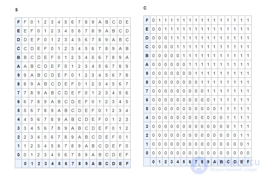
It consists of two 16×16 tables. The first table gives the sums modulo 16, the second table gives the carry units in binary (two-operand) hexadecimal addition.

Comments