
Lecture
In addition to parity-checking circuits, another node that belongs to the control circuits and is used to build highly reliable digital circuits is the majority element.
In any device, disruptions of normal operation are possible – failures (errors), which can arise both because of the occurrence of faults and because of the effects of interference. One method of increasing the reliability of digital systems is to detect and subsequently eliminate the errors that arise.
However, in a number of cases their occurrence is unacceptable, that is, the probability of an error must be reduced to zero. In such situations, redundancy of nodes, units, and individual pieces of equipment is used. That is, several devices are put into operation in parallel and solve one and the same task. If they function correctly, they produce identical results. In most situations, if some of them malfunction or fail, the rest will continue to function normally. In this case, ensuring reliable operation of the system requires some node that would pass through to its output only the signals coming from the correctly functioning units.
One way of solving this problem consists in using majority elements, whose operation can be described as follows. Suppose the system uses triple duplication,
that is, there are three identical nodes  , which, under normal operation, produce identical single-bit binary signals
 .
.
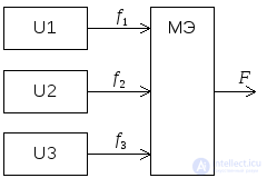 If one of them malfunctions, its signal turns out to be the opposite of the ones produced by the other two. In this case, the correct value of the output signal must match the state of the majority of the devices.
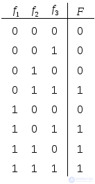 The table describing the operation of a three-input majority element has the following form. At its output a signal is produced that is identical to the majority of those arriving at its inputs. The function describing the operation of such a device is given by the expression
 .
.

 Using the rules of logic algebra, or by constructing a Karnaugh map, this expression can be simplified to
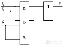
 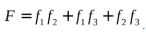 . The internal structure of such an element has the following form, and on schematic diagrams it is depicted as follows.
It is evident that a majority element can have only an odd number of inputs, 3, 5, 7, and so on, since otherwise, with an equal number of correct and incorrect signals, no decision can be made about which to choose. In addition, the majority element itself is required to have very high reliability, since if it fails, the entire redundancy scheme becomes useless.
It is fairly simple to create a device that, in a circuit with a majority element, produces the binary code of the number of the node generating the false signal. The table of its operation has the following form. A code of zero corresponds to the correct functioning of all nodes, that is, all signals coinciding, whereas otherwise the code produced is the number of the device whose output state does not coincide with the rest.
A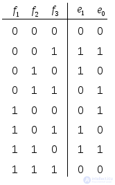 nalytical expressions for the functions describing the corresponding bits
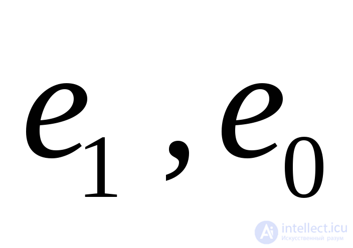 , can be obtained using a Karnaugh map; however, having analysed the structure of the table, one can see that the values
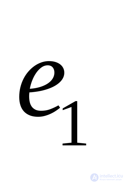 do not depend on
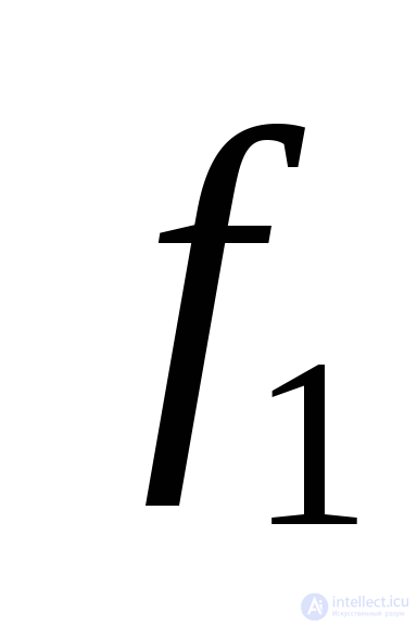 and are described by the logical non-equivalence function for the signals
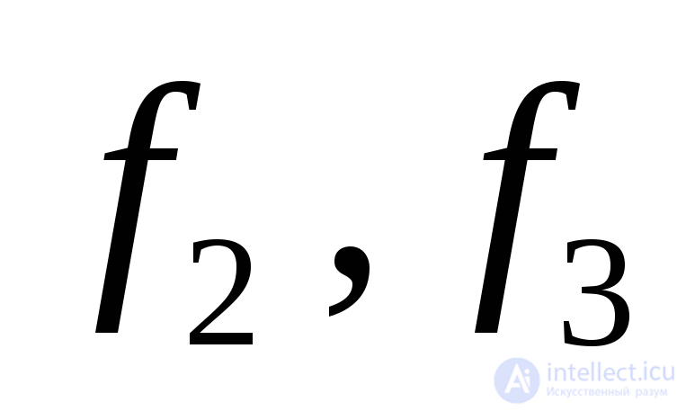 , that is
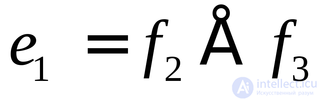 . The bit
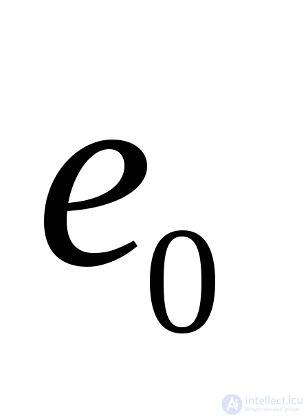 in the first four rows of the table coincides with
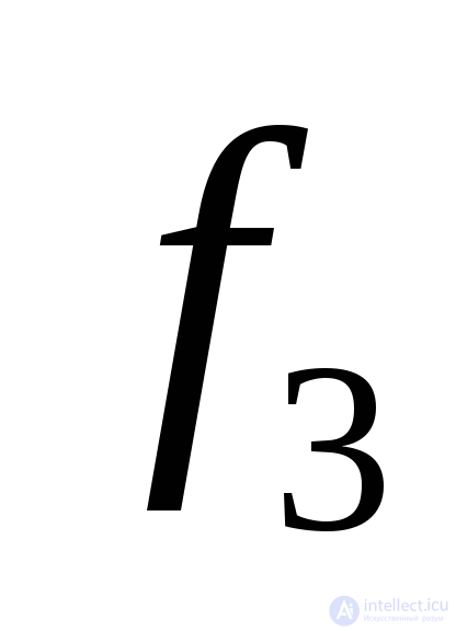 , and in the rest takes values that are inverse with respect to this function. Here the direct forms are realised when
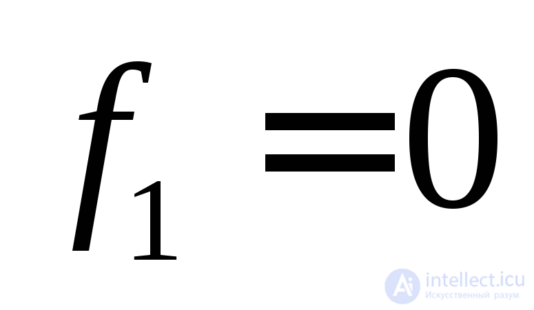 , and the inverted ones when
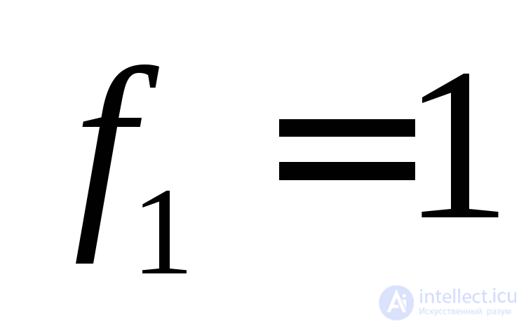 , regardless of the state of
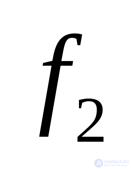 . Thus, to realise
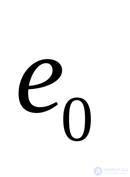 one can use controlled inversion of
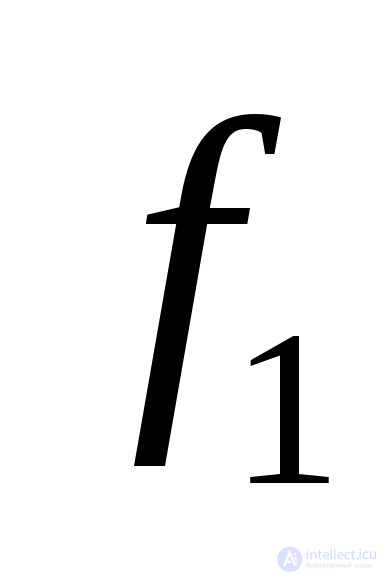
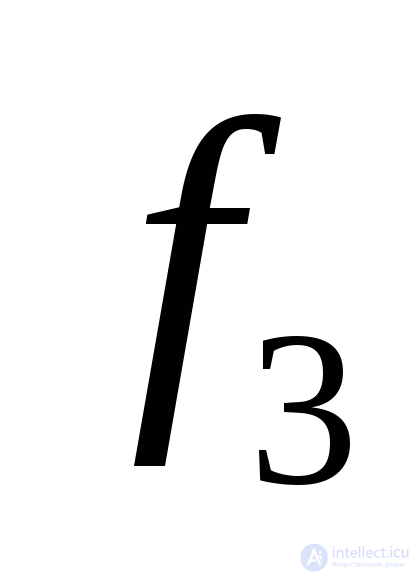 by the unit value of
 . This procedure corresponds to carrying out the logical non-equivalence function
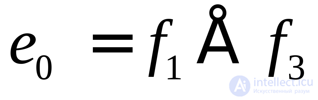 and is implemented by a logic element – a modulo-two adder.

Comments